Spindle motor having a hydrodynamic bearing system

Inactive Publication Date: 2005-10-13
MINEBEAMITSUMI INC
View PDF23 Cites 48 Cited by
  • Summary
  • Abstract
  • Description
  • Claims
  • Application Information

AI Technical Summary

Benefits of technology

[0006] It is thus the object of the invention to provide a spindle motor having a hydrodynamic bearing system that allows the

Problems solved by technology

Due to the short joint length between the rotor and the shaft, however, it could happen that the rotor tilts with respect to the shaft when the platters are mounted onto the rotor, resulting in an increase in the radial and axial runout.
If the overall length of the motor remains the same, however, the useful length of the radial bearing is decreased as a con

Method used


Image

  • Spindle motor having a hydrodynamic bearing system
  • Spindle motor having a hydrodynamic bearing system
  • Spindle motor having a hydrodynamic bearing system

Examples


Embodiment Construction

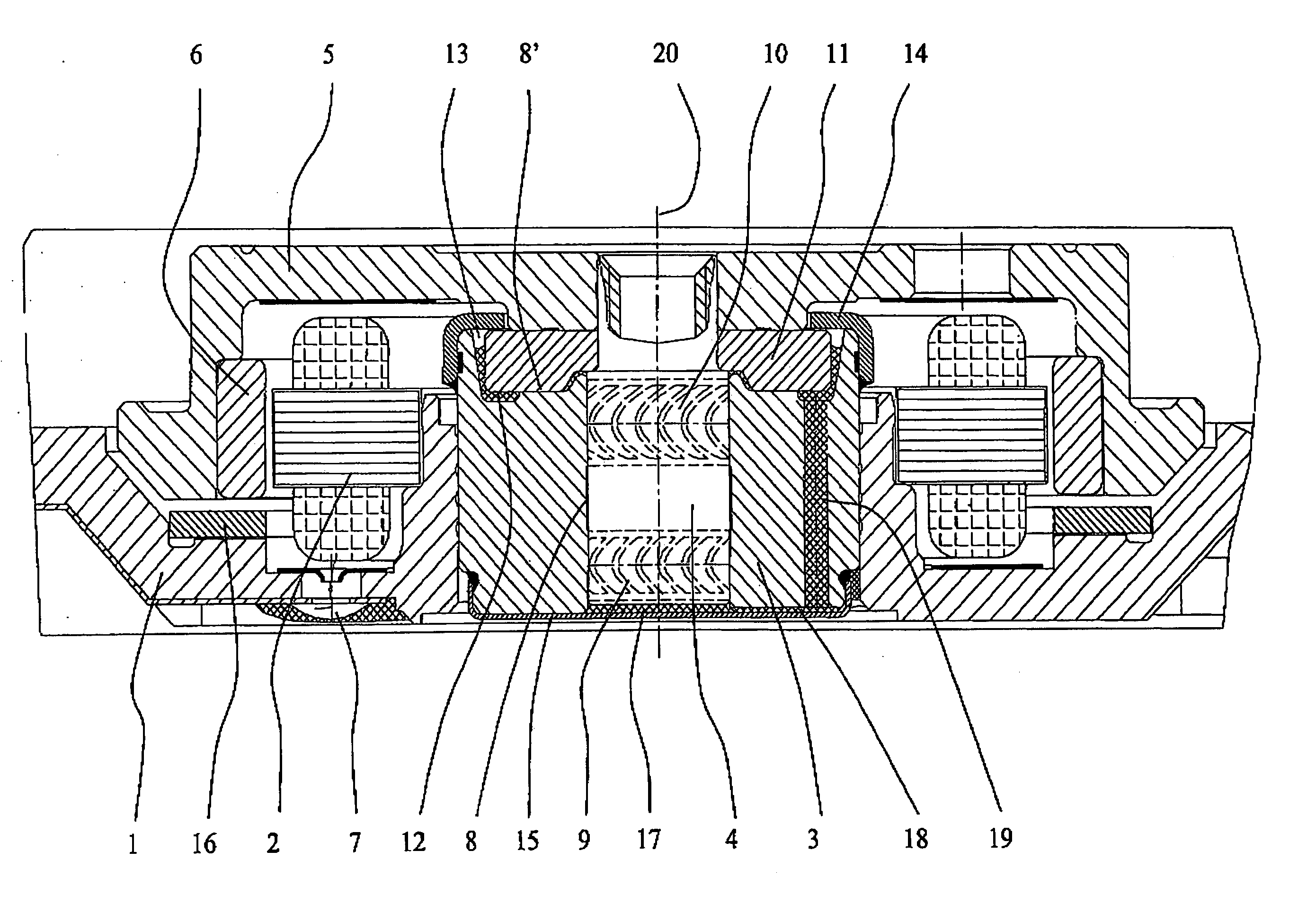
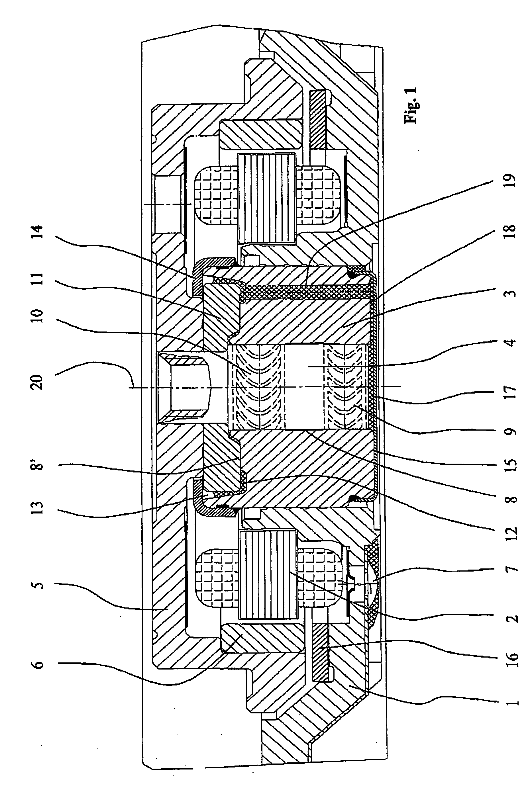
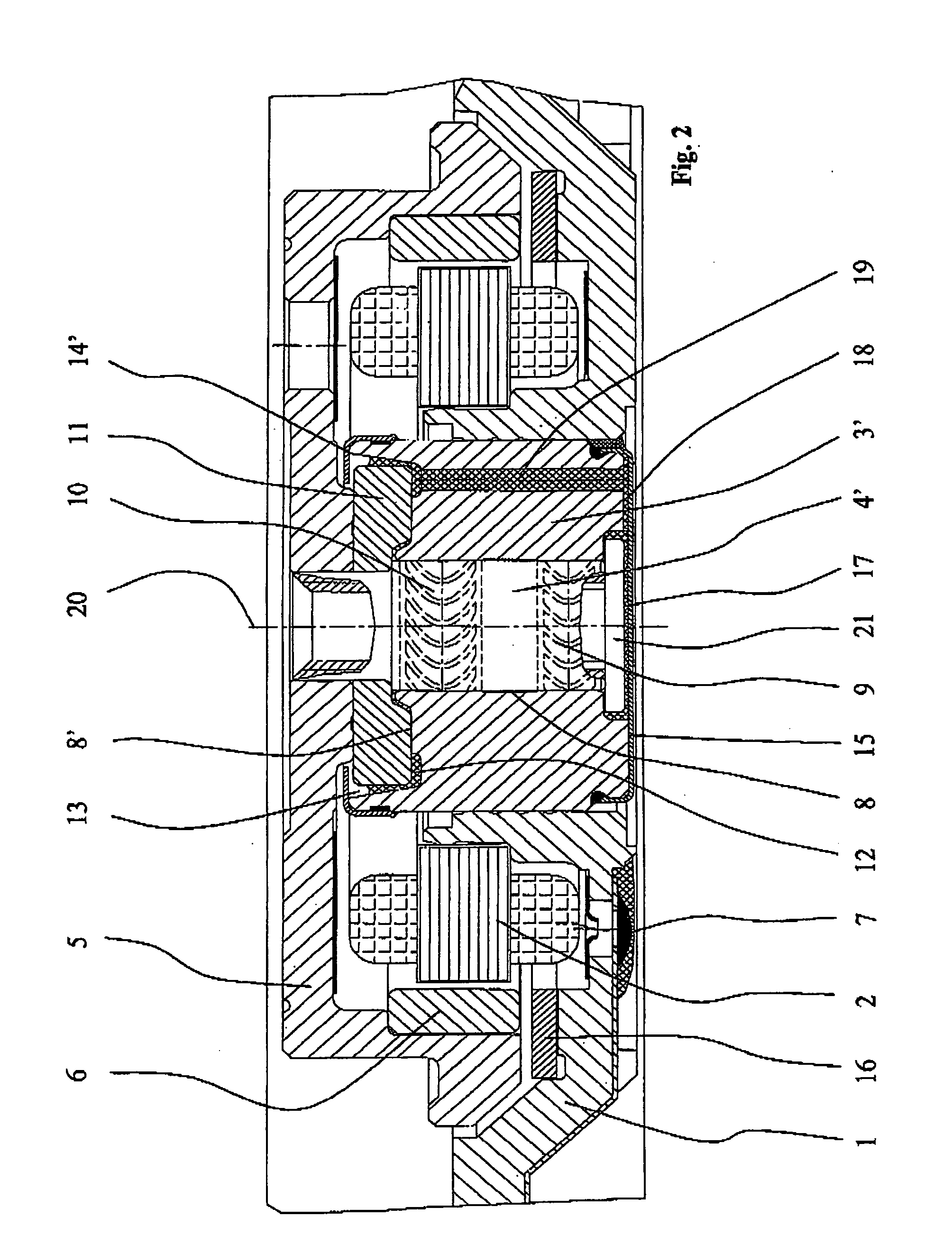
[0032] All the spindle motors illustrated in FIGS. 1 to 6 comprise a stationary baseplate 1 on which a stator arrangement 2 consisting of a stator core and windings is arranged. A bearing sleeve 3 or 3′ is firmly accommodated in a recess in the baseplate 1 and has a cylindrical axial bore in which a shaft 4 or 4′ is rotatably accommodated. The free end of the shaft 4 or 4′ carries a rotor hub 5 or 5′ on which one or more platters (not illustrated) of the hard disk drive are arranged and fixed. An annular permanent magnet 6 having a plurality of pole pairs is arranged at the lower inside edge of the rotor hub 5 or 5′, an alternating electrical field being applied to the pole pairs by a stator arrangement 2 spaced apart from them by means of an air gap, so that the rotor 5 or 5′, together with the shaft 4 or 4′, is set in rotation about the rotational axis 20. The stator windings are supplied with power, for example, via electrical contacts 7.

[0033] A bearing gap 8 remains between th...


PUM


Abstract

The invention relates to a spindle motor having a hydrodynamic bearing system, particularly to drive platters in a hard disk drive, the platters being disposed on a rotor, and the bearing system being formed by a bearing sleeve arranged on a baseplate and a shaft rotatably supported in an opening in the bearing sleeve and at least one thrust plate connected to the shaft. A liquid lubricant is filled into a bearing gap formed between the shaft, the thrust plate and the bearing sleeve. The invention is characterized in that the thrust plate rests directly against the rotor and is accommodated in an annular recess in the bearing sleeve facing the rotor.

Description

BACKGROUND OF THE INVENTION [0001] The invention relates to a spindle motor having a hydrodynamic bearing system, particularly a spindle motor to drive the platters in a hard disk drive according to the preamble of patent claim 1. PRIOR ART [0002] A spindle motor having a hydrodynamic bearing system, as revealed for example in DE 202 11 588 U1, comprises a stationary baseplate on which a stator arrangement consisting of a stator core and windings is arranged. A shaft is rotatably accommodated in a bearing sleeve. A rotor is disposed at the free end of the shaft, one or more platters (not illustrated) of the hard disk drive being arranged and fixed on the rotor. An annular permanent magnet having a plurality of pole pairs is arranged at the lower inside edge of the rotor hub, an alternating electrical field being applied to the pole pairs by a stator arrangement spaced apart from them by means of an air gap, so that the rotor, together with the shaft, is put into rotation. A bearing ...

Claims


Application Information

Patent Timeline
IPC IPC(8): F16C17/10F16C17/04F16C32/06F16C33/10F16C33/74G11B17/02H02K5/16H02K7/08
CPCF16C17/102H02K5/1675F16C2370/12
Inventor HAFEN, MARTINHOFFMANN, JOERGKULL, ANDREASKIRCHMEIER, TOBIASNEUMANN, RUDOLFREHM, THILOWINTERHALTER, OLAF
Owner MINEBEAMITSUMI INC
Why Eureka
Try Eureka