
Brush card assembly with RFI suppression for two or three speed permanent magnet brush motor with link wound dual commutator and dual armature winding configuration

Inactive Publication Date: 2005-10-13
SHUFFLE MASTER +1
View PDF5 Cites 16 Cited by
  • Summary
  • Abstract
  • Description
  • Claims
  • Application Information

AI Technical Summary

Benefits of technology

[0018] In accordance with yet another aspect of the invention, a brush holder structure is provided for a brush card assembly. The brush card assembly has a brush card of generally circular configuration having a central opening there-through. The brush card assembly carries a plurality of brushes and a spring is associated with each brush to bias the associated brush towar

Problems solved by technology

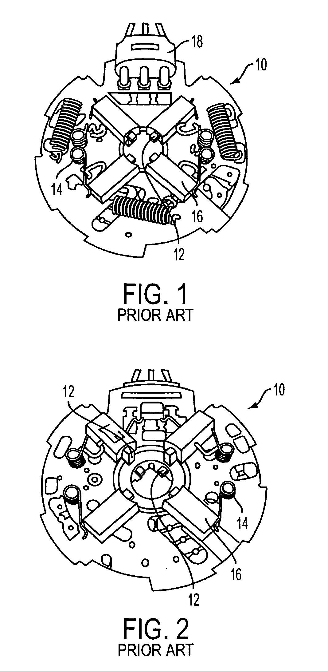
The current two speed motor configuration with dual-armature winding and two commutators is not cost competitive on the market compared to a two speed solution such as adding a resistor in series with the motor.

Method used


Image

  • Brush card assembly with RFI suppression for two or three speed permanent magnet brush motor with link wound dual commutator and dual armature winding configuration
  • Brush card assembly with RFI suppression for two or three speed permanent magnet brush motor with link wound dual commutator and dual armature winding configuration
  • Brush card assembly with RFI suppression for two or three speed permanent magnet brush motor with link wound dual commutator and dual armature winding configuration

Examples


Embodiment Construction

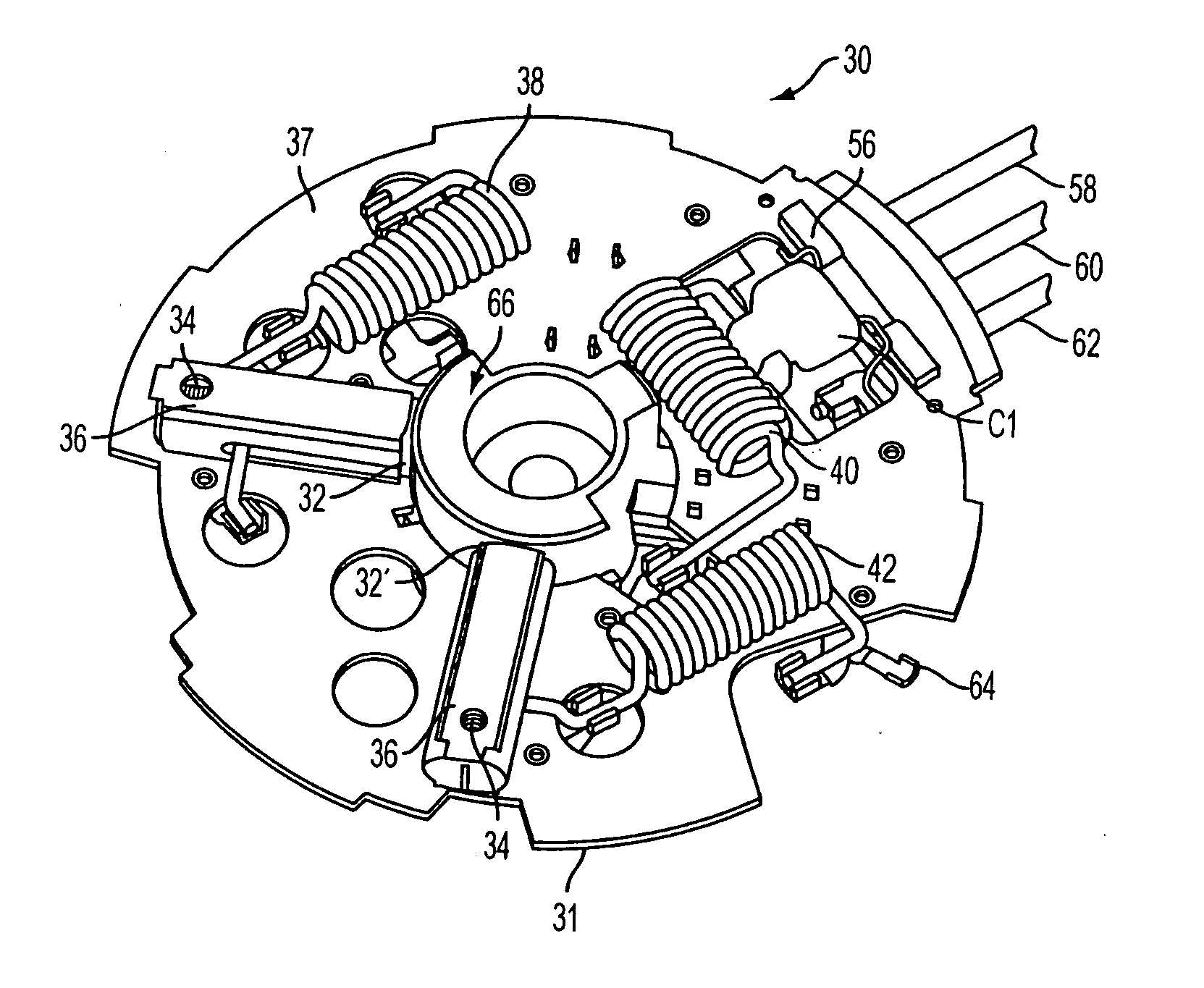
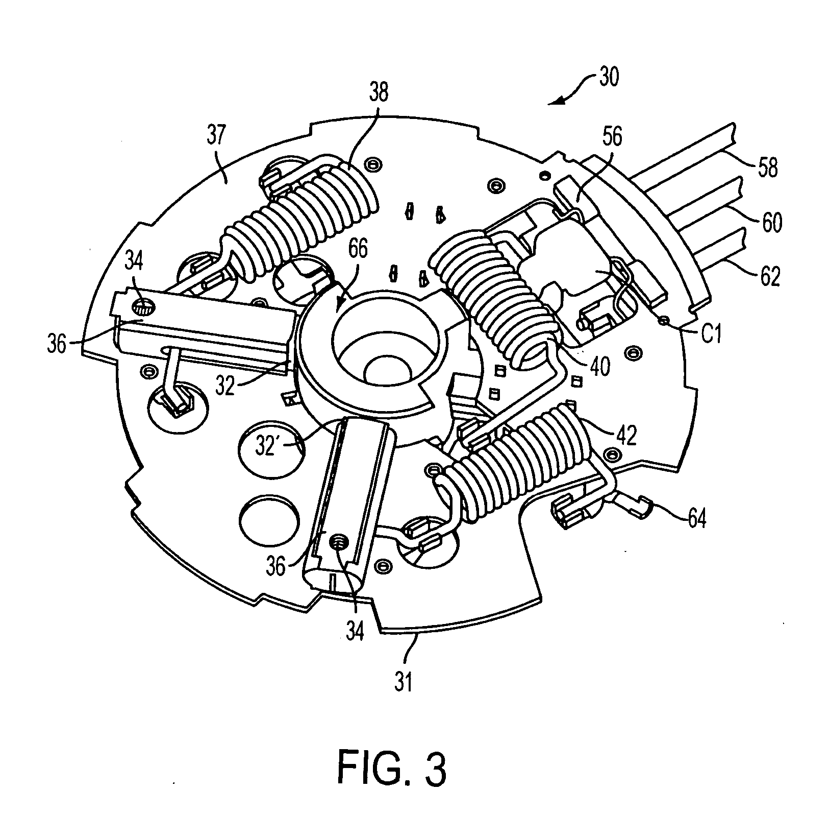
[0029] With reference to FIGS. 3 and 4, a brush card assembly, generally indicated at 30, is shown in accordance with the principles of the invention. The brush card assembly 30 is a subcomponent (assembly) of a motor configuration with link wound dual commutators and dual-armature winding configuration. The link wound technology is also well known in the art and is disclosed, for example, in U.S. Pat. No. 6,694,599, the contents of which is hereby incorporated into the present specification by reference.

[0030]FIG. 3 shows the high speed (HS) side 37 and FIG. 4 shows the low speed (LS) side 35 of the same brush card 31 of the brush card assembly 30. As shown in FIG. 3, there is a pair of brushes (positive brush 32 and negative brush 32′), brush springs 34, and brush tubes 36 at the HS side 37 of the brush card assembly 30. Also, there is a pair of brushes (positive brush 33 and negative brush 33′), brush springs 34′, and brush tubes 36′ at the LS side 35 of the brush card assembly ...


PUM


Abstract

A brush card assembly 30 is provided for a permanent magnet brush motor 50. The motor includes a link wound, high speed side commutator 46 and an associated high speed side armature winding 44, and a link wound low speed side commutator 54 and an associated low speed side armature winding 52. The brush card assembly includes a brush card 31 including a high speed side having a positive brush 32 and a negative brush 32′ constructed and arranged to be operatively associated with the high speed side commutator 46, and a low speed side opposite the high speed side. The low speed side has a positive brush 33 and a negative brush 33′ constructed and arranged to be operatively associated with the low speed side commutator 54. The brushes are constructed and arranged with respect to the commutators to provide at least two different operating speeds of the motor.

Description

[0001] This application is based on U.S. Provisional Application No. 60 / 560,457, filed on Apr. 8, 2004, and claims the benefit thereof for priority purposes.FIELD OF THE INVENTION [0002] The invention relates to permanent magnet direct current brush motors (PMDC BM) for automotive applications such as, engine cooling, Heating, Ventilation and Air Conditioning (HVAC), or Anti-lock Braking System (ABS). BACKGROUND OF THE INVENTION [0003] Often, permanent magnet motors used in automotive applications require the use of more than one speed, usually a lower speed for general-purpose operation and a maximum speed for worst-case operation. Multiple speed operation of the cooling system module provides a more optimized engine temperature and operation, which consequently contributes to improved fuel economy. [0004] For PMDC BM historically lower speeds (multiple speed operation) have been achieved by the following methods: [0005] Adding a resistor in series with the motor [0006] Switching o...

Claims


Application Information

Patent Timeline
IPC IPC(8): H02K1/00H02K5/14H02K11/02H02K13/00H02K23/36
CPCH02K5/148H02K11/026H02K23/36
Inventor SIMOFI-ILYES, ATTILALAKERDAS, ANDREWSMOROWSKI, STEFAN ZENONVAN HORNE, STEVEN RUSSELLKONCAN, MICHAEL JOHN
Owner SHUFFLE MASTER
Learn More