Screen and image projector using the screen

a projector and screen technology, applied in the field of screen and image projector using the screen, can solve the problems of low gain, narrow field of view of the screen, and dark screen, and achieve good brightness characteristics, good contrast, and good viewing angle characteristics

Inactive Publication Date: 2005-10-13
YAMAUCHI NAOFUMI
View PDF5 Cites 29 Cited by
  • Summary
  • Abstract
  • Description
  • Claims
  • Application Information

AI Technical Summary

Benefits of technology

[0006] An object of the present invention is to provide a thin, light weight projector screen having good viewing angle characteristics, good brightness characteristics, and good contrast.

Problems solved by technology

Problems as described below exist, however, with conventional techniques.
Although a wide field of view can be achieved with a screen made by using diffusion materials such as beads, the screen becomes dark due to low gain.
Further, although a bright screen having a high gain can be obtained by using lenticular lenses due to high directionality, the field of view of the screen becomes narrow.
Furthermore, screens used in projectors that employ lenticular lenses are manufactured by forming transparent resins such as acrylic resins, and the manufacturing process thus cannot be made low cost.
In addition, image quality degradation becomes large for a medium or small size screen on the order of 8 to 20 inches when viewing an image at a short distance from the screen.

Method used


Image

  • Screen and image projector using the screen
  • Screen and image projector using the screen
  • Screen and image projector using the screen

Examples


embodiment 1

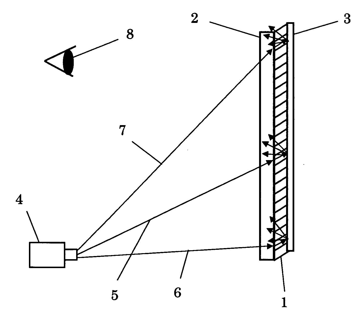
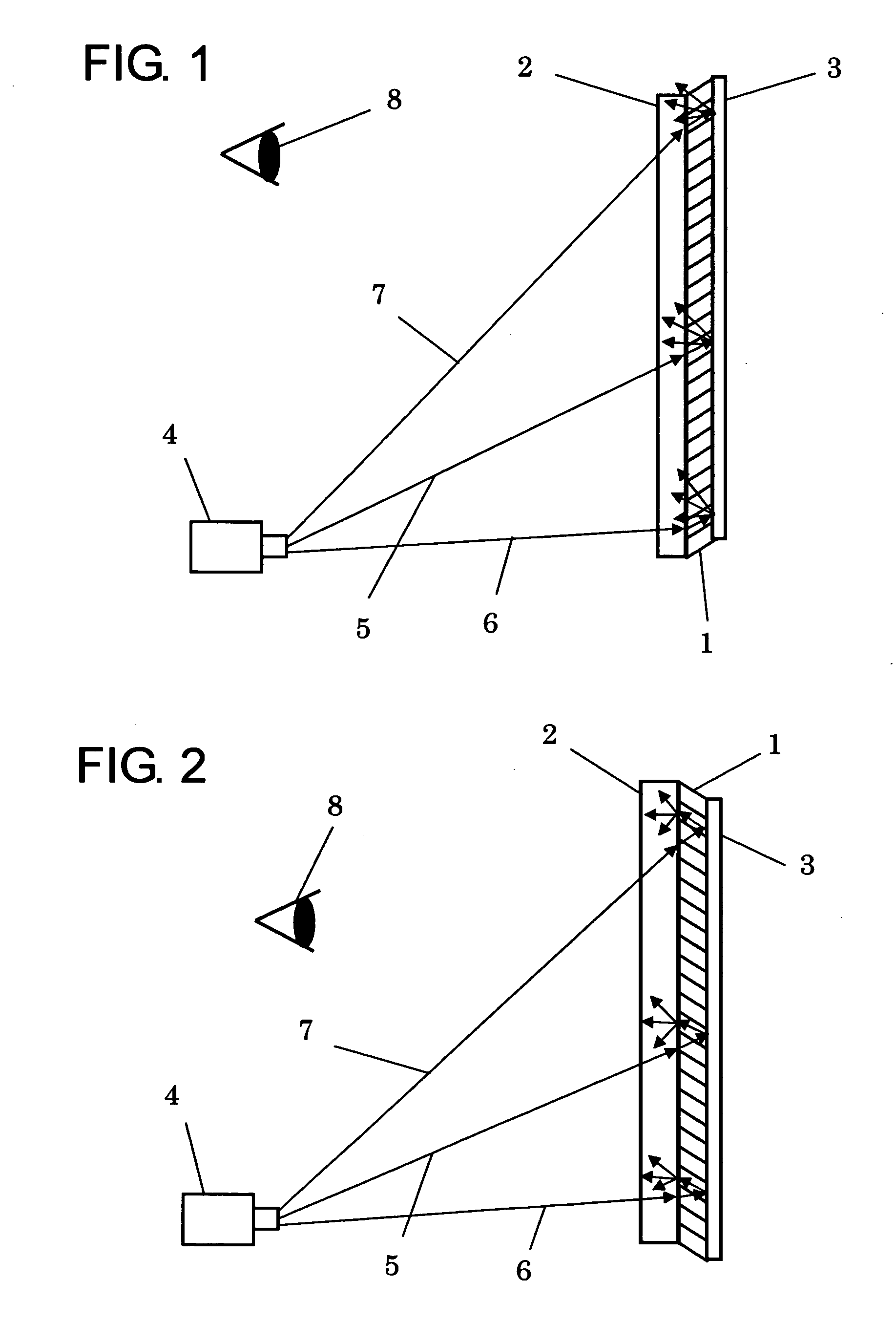
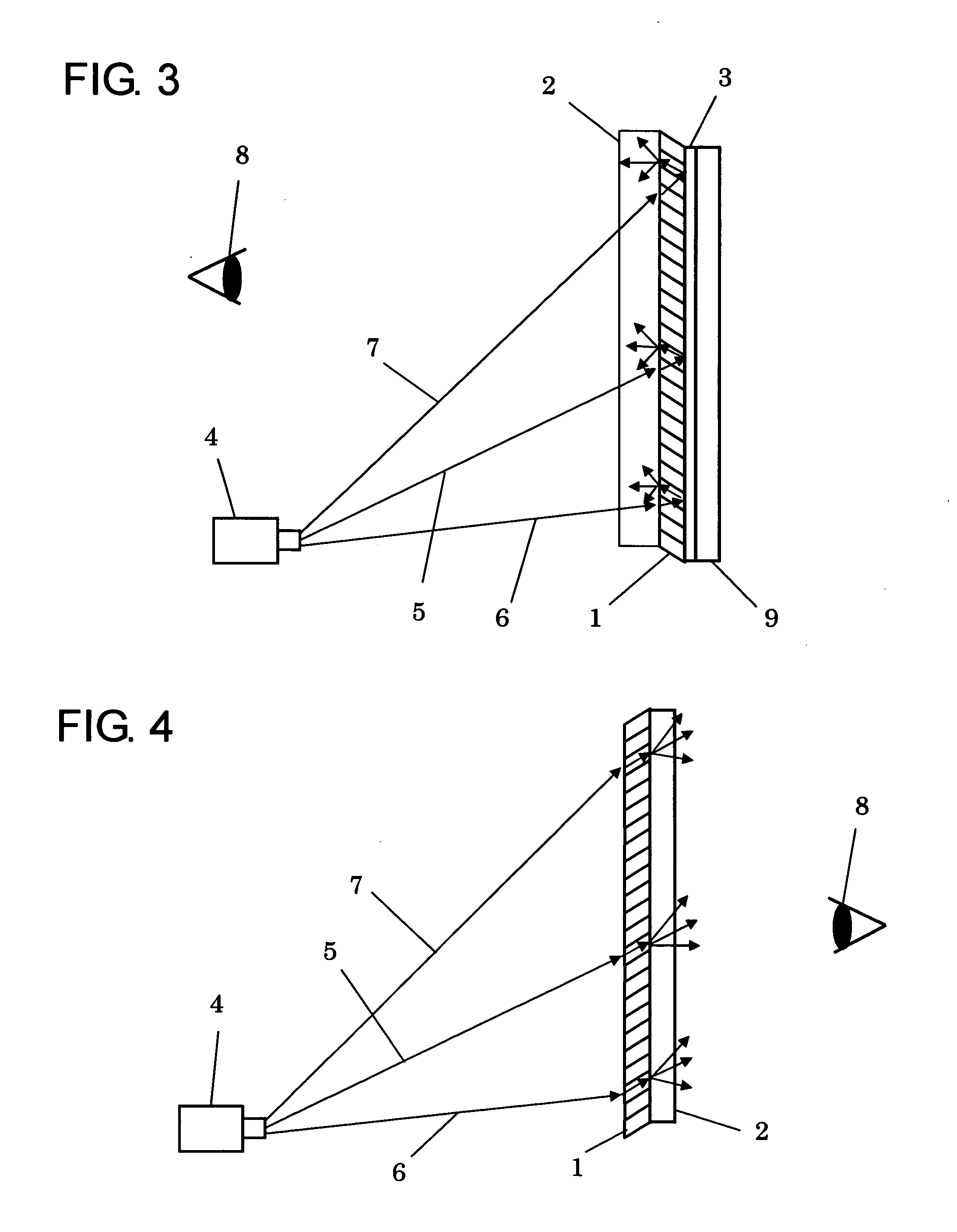
[0040]FIG. 1 schematically shows a cross sectional configuration of a screen and a projector arrangement according to Embodiment 1. Referring to FIG. 1, an optical image from a projector 4 is projected onto a screen that includes a column-shaped lens sheet 1, a transparent substrate 2, and an optical reflecting layer 3. The projected image is observed through the screen by an observer 8, who is on the same side as the projector 4. Screens used in this manner are called front screens. An optical axis direction of a column-shaped lens is referred to as an orientation direction. With the configuration shown in FIG. 1, orientation directions of column-shaped lenses substantially coincide with an optical axis 5 direction of the optical image projected from the projector 4. In other words, the column-shaped lenses are arranged within the plane of the column-shaped lens sheet so as to be inclined downward. The column-shaped lens sheet is a film having a plurality of column-shaped lenses ar...

specific example 1

[0050] The screen configured as shown in FIG. 1 was manufactured. While projecting a white color image, changes in the screen front surface brightness were investigated by changing the incoming angle of the optical axis of the projected image into the orientation direction of the column-shaped lens sheet. The spread angle of the white color image was ±2 degrees. A column-shaped lens sheet having lenses with a lens diameter of 20 μm and a sheet thickness of 70 μm was used as the column-shaped lens sheet. Two kinds of graded index lens sheets having orientation directions of 0 degrees and 15 degrees, respectively, and a maximum index of refraction between the high index of refraction region and the low index of refraction region of 0.02, were used. An optical reflecting layer having a reflectance of 34% was formed on a rear surface of the column-shaped lens sheet by forming approximately 19 nm of an Ag and Pd alloy using vacuum evaporation. A sample in which the column-shaped lens she...

specific example 2

[0054] Using a structure similar to that used in Specific Example 1, changes in brightness at the front surface of the screen were investigated by changing the incoming angle of the optical axis of the white color image to be a right angle with respect to the orientation direction of the column-shaped lens sheet. Measurement results are shown in FIG. 19. The curve22 shows a case where the orientation direction of the column-shaped lens sheet was zero degrees, while a curve 23 shows a case where the orientation direction of the column-shaped lens sheet was 15 degrees. From the results it can be seen that light projected from a direction perpendicular to the orientation direction of the column-shaped lens sheet is scattered similar to cases where the column-shaped lenses are oriented perpendicularly, regardless of the orientation angle of the column-shaped lens sheet. Further, it could be verified that transmitted light that is transmitted at an incoming angle greater than 15 degrees ...


PUM

PropertyMeasurementUnit
sizeaaaaaaaaaa
thicknessaaaaaaaaaa
diameteraaaaaaaaaa

Abstract

A projector screen having a simple configuration, which provides a wide field of view angle and can be used for both transmission and reflection projection is achieved. A screen according to the present invention is provided with a directional scattering layer that scatters incoming light within a specific angular range and transmits incoming light outside the specific angular range. Further, an image projection system can be made by combining the screen with an image projector that projects an image onto the screen.

Description

BACKGROUND OF THE INVENTION [0001] 1. Field of the Invention [0002] The present invention relates to a screen on which an optical image is projected from a high brightness CRT, a liquid crystal projector, or a projector that uses a micromirror device. The present invention also relates to an image projector system that uses the screen. [0003] 2. Description of the Related Art [0004] Image projector systems such as projector devices that display images by projecting optical images utilizing a high brightness CRT, a liquid crystal projector, a projector using a micromirror device, or the like can simply and easily display a high definition image on a large screen. Consequently, image projector systems are widely used as information communication tools among a plurality of users. The light utilization efficiency of an image projector system may be increased by using a structure in which a white color material or a reflective film is used to cover a surface of the screen, and the visibi...

Claims


Application Information

Patent Timeline
Patent Type & Authority Applications(United States)
IPC IPC(8): G02B5/02G03B21/60G02F1/1335G03B21/00G03B21/56H04N5/74H04N9/31
CPCG03B21/60
Inventor YAMAUCHI, NAOFUMI
Owner YAMAUCHI NAOFUMI
Why Eureka
Try Eureka