Object recognition system for vehicle

Active Publication Date: 2005-10-13
DENSO CORP
View PDF8 Cites 18 Cited by
  • Summary
  • Abstract
  • Description
  • Claims
  • Application Information

AI Technical Summary

Benefits of technology

[0011] The present invention has been made to solve the above-described problem and, therefore, an object of the present invention is to provide an object recognition d

Problems solved by technology

Accordingly, in the case where the above phenomenon becomes remarkable, it is judged as the condition in which the stain or water droplets adhere to the sensor surface, that is, the adverse cond

Method used


Image

  • Object recognition system for vehicle
  • Object recognition system for vehicle
  • Object recognition system for vehicle

Examples


Embodiment Construction

[0069] Now, a description will be given in more detail of preferred embodiments of the present invention with reference to the accompanying drawings.

[0070] In this embodiment, an object recognition device is applied to a vehicular gap control device.

[0071] First, the systematic structure of this embodiment will be described.

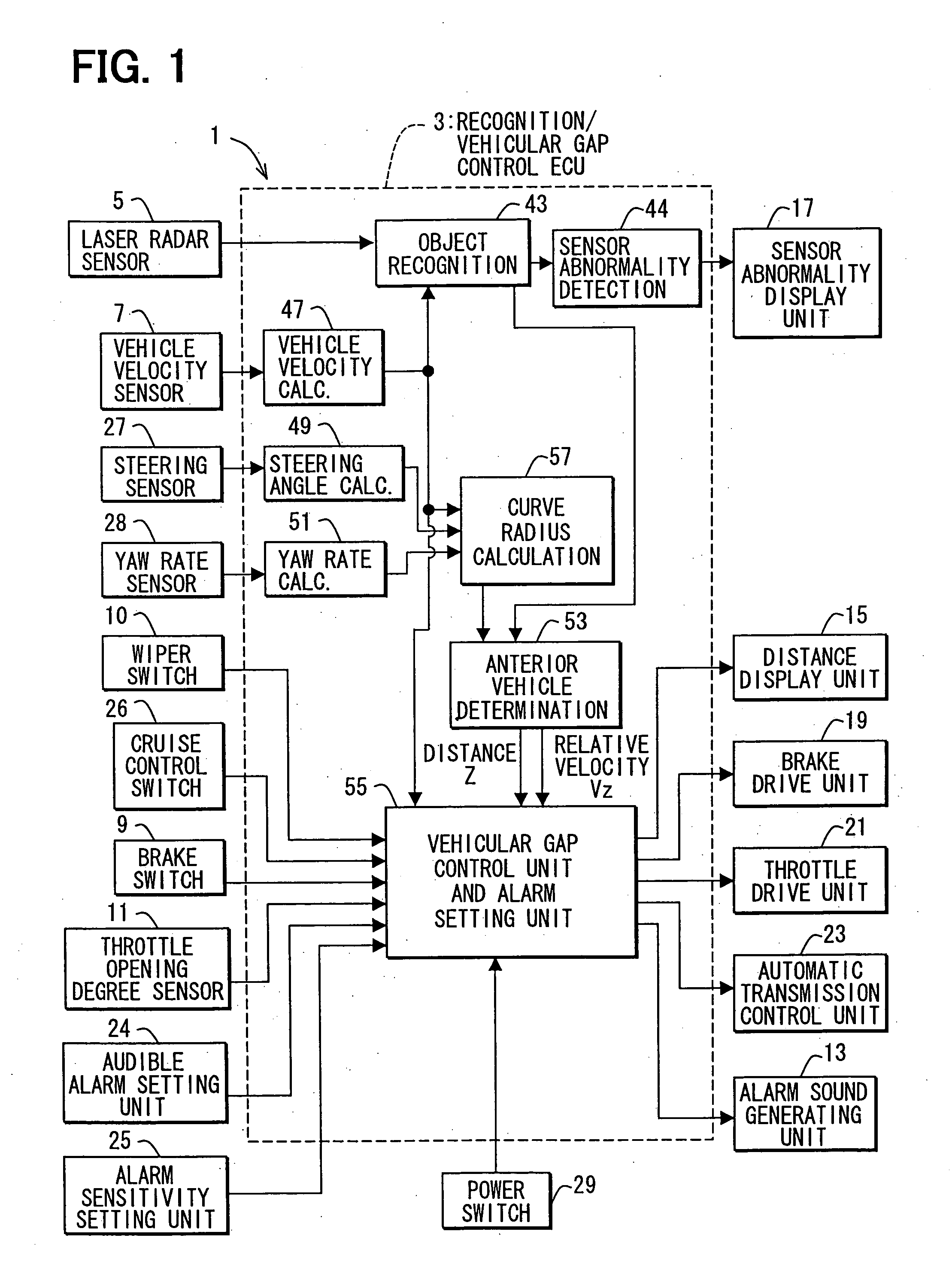
[0072]FIG. 1 is a system block diagram showing a vehicular gap control device 1.

[0073] The vehicular gap control device1 is mainly made up of a recognition / vehicular gap control ECU 3. The recognition / vehicular gap control ECU 3 is mainly made up of a microcomputer and includes an input / output interface (I / O). Those hard structures are general, and therefore their detailed description will be omitted.

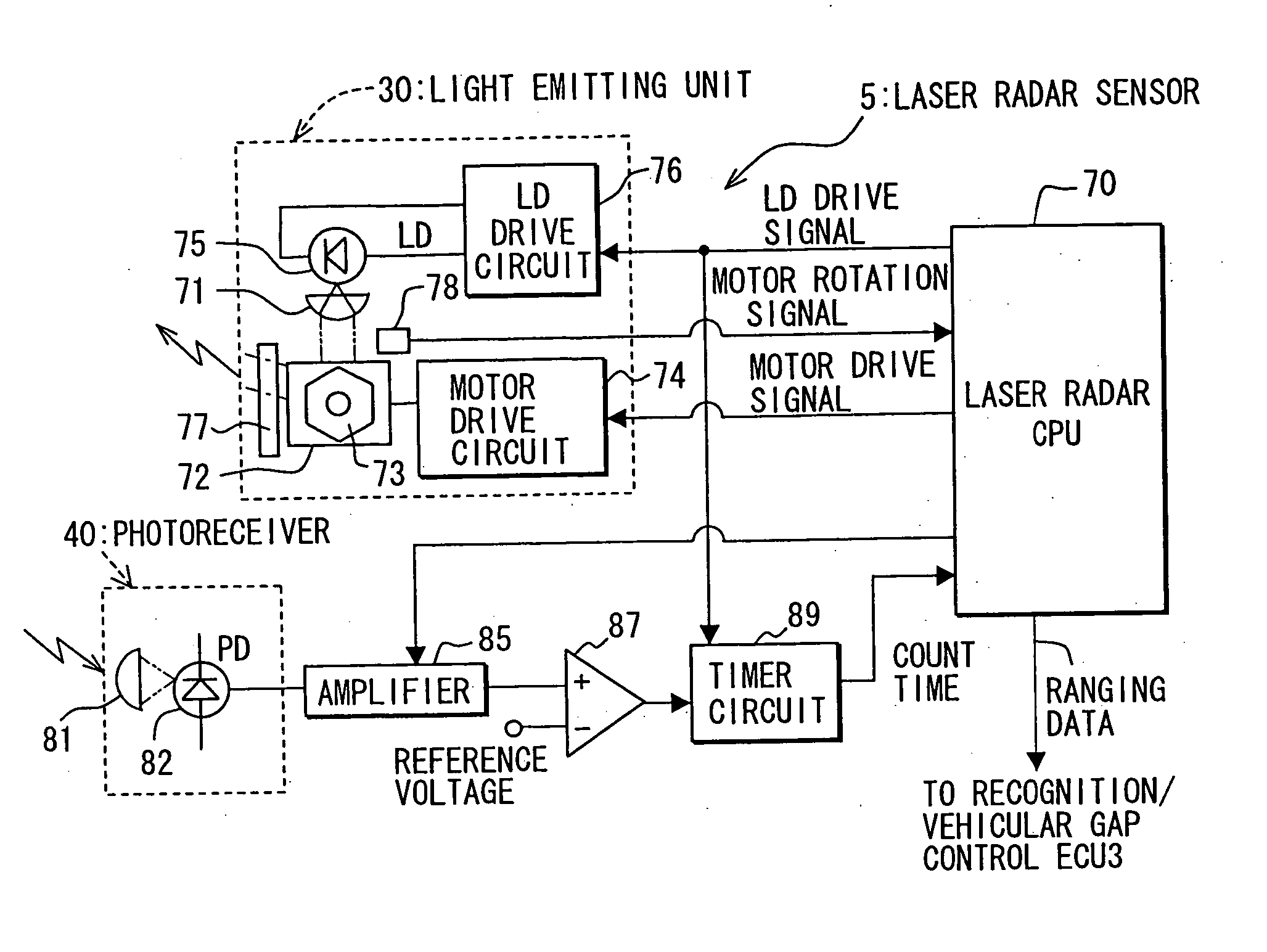
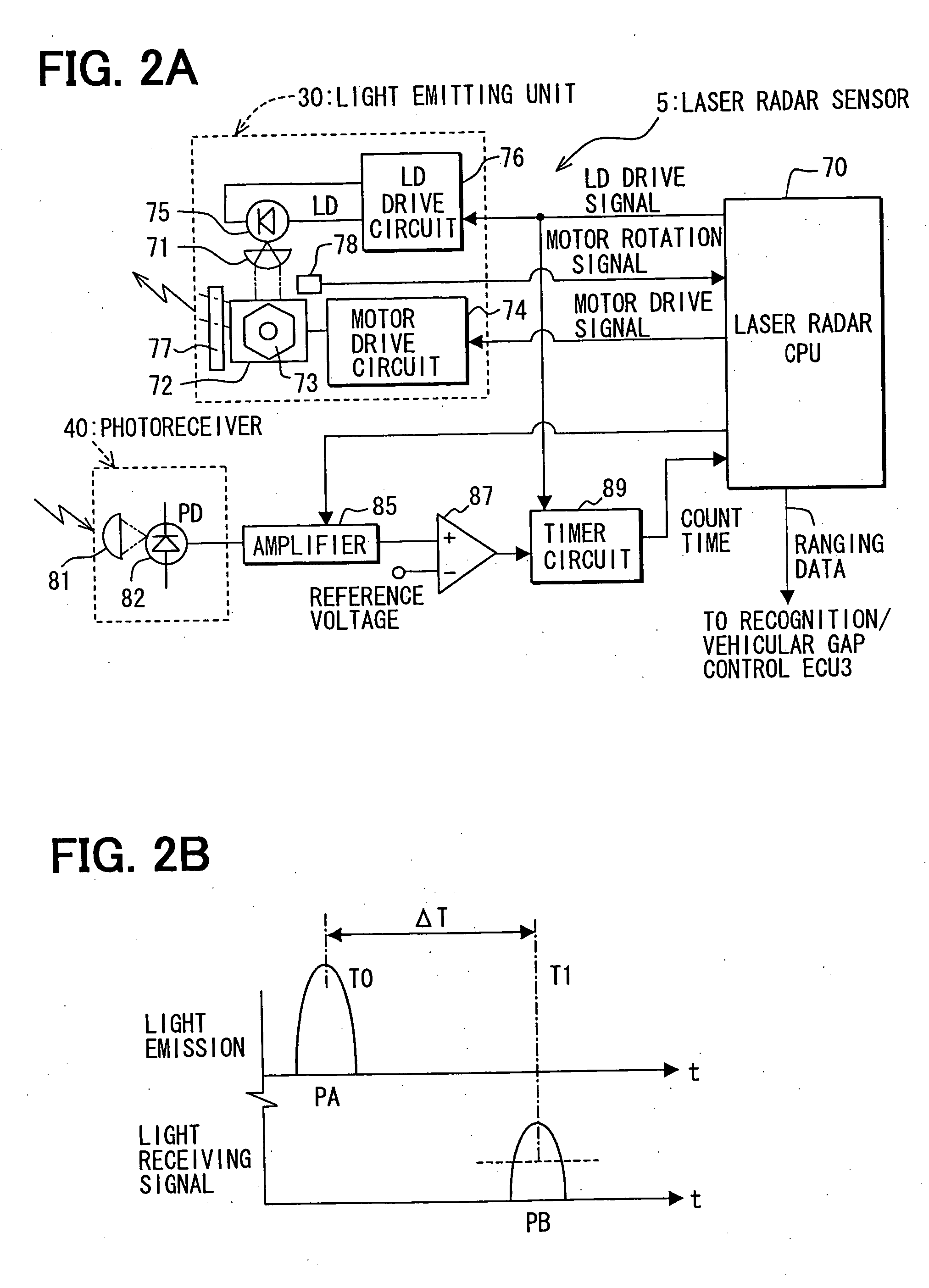
[0074] The recognition / vehicular gap control ECU 3 inputs the respective detection signals from a laser radar sensor 5, a vehicle velocity sensor 7, a brake switch 9, a wiper switch 10 and a throttle opening sensor 11, and outputs drive signals to an audible ala...


PUM


Abstract

An object recognition device for a vehicle includes a size determining means, an existence condition determining means, and an adverse condition determining means. The size determining means determines that the recognized objects are large when a size of the objects is larger than a given determination value. The existence condition determining means determines whether at least a given number of the objects are determined to be large by the size determining means. The adverse condition determining means identifies an adverse condition related to recognizing the objects when at least the given number of the objects are determined to be large by the existence condition determining means.

Description

CROSS REFERENCE TO RELATED APPLICATIONS [0001] This application is based upon and claims the benefit of priority of Japanese Patent Application No. 2004-115588, filed on Apr. 9, 2004, the contents of which are incorporated herein by reference. FIELD OF THE INVENTION [0002] The present invention relates to an object recognition device for a vehicle and, more particularly, an object recognition device and program for recognizing an object in front of the vehicle based on transmitted and reflected waves. BACKGROUND OF THE INVENTION [0003] Up to now, there has been proposed an object recognition device that irradiates transmitting waves such as light waves or millimeter waves over a given angle in front of the subject vehicle. The device then detects reflected waves to recognize an object (target) in front of the subject vehicle. [0004] This type of device detects an interval between the subject vehicle and an anterior vehicle. When the interval becomes shorter, an alarm is generated or...

Claims


Application Information

Patent Timeline
IPC IPC(8): B60R21/00B60W40/02G01B11/24G01B11/30G01C3/08G01P3/36G01S7/40G01S7/41G01S17/14G01S17/42G01S17/86G01S17/931G06K9/00G08G1/16
CPCB60W40/02G01S17/023G01S17/105G06K9/00805G01S17/936G08G1/16G01S2007/4975G01S17/42G08G1/165G08G1/166G01S17/14G01S17/86G01S17/931G06V20/58
Inventor SAMUKAWA, YOSHIENATSUME, TSUTOMUOKUDA, KEIKO
Owner DENSO CORP
Why Eureka
Try Eureka