Method and apparatus to correct distortion of document copies

a document copy and distortion technology, applied in the field of improving the quality of copies, can solve the problems of skew in the output copy, distortion in the output copy, and skew in the printing information (e.g., text, graphics, etc.) near the binding, and achieve the effect of less than satisfactory approach

Inactive Publication Date: 2005-10-13
INT BUSINESS MASCH CORP
View PDF4 Cites 27 Cited by
  • Summary
  • Abstract
  • Description
  • Claims
  • Application Information

AI Technical Summary

Benefits of technology

[0012] It is an objective of the present invention to provide an improved method for correcting distortion in scanned images of pages in a bound volume before that image is output to a user.
[0013] It is another objective of the method of the present invention to correct distortion in copied documents without the expense of costly hardware added to the copy machine.
[0014] It is another objective of the method of the present invention to allow for other post-processing of documents copies or produced using simple and inexpensive means.
[0016] According to the invention, there is provided a tape of sticking paper marked with equidistant lines, called bars, along the length of the tape. The tape is preferably transparent and rather narrow. The tape is easily attached (in one or more strips) to a page to be copied, parallel (or about) to lower and upper boundaries, preferably at a place(s) (e.g., close to the boundary(ies)) where it does not obstruct (too much of) the text or images. This tape can remain on the page permanently or can be detached easily after use, depending on the choice of quality, which in turn will determine the kind of use one intends. Optionally, the bars can be printed on the page by the printer or publisher of the volume to eliminate the need for strips altogether.
[0017] In the case a page is copied using a classical copy machine, not equipped with any distortion device, the bars will appear on the copy but will not be equidistant, and possibly not exactly aligned. Nevertheless, they will be (quasi) equidistant and aligned near the outer boundary of the page (by which we mean the portion of the page copied from the outer boundary of the book or the like). Thus, the bars collection can be easily recognizable using specialized software, which can be equipped in some other copy machine or some other computation device. A further processing of the page copies with distortion by such a machine then allows obtaining much better copies. If the tape is not placed exactly parallel to the bottom of the page, this will be easily recognized by inspection of the outer part of the set of bars and can be corrected by the software. In the case a page is copied using a copy machine equipped with such specialized software, the correction of the distortion can be made at the first print. Since the software allows for recognition of the bars, one may choose to avoid displaying a copy of the bars on the copy. This is easily done since the specialized software recognizes the collection of bars.
[0019] A further advantage is that the method can be performed without having the full page or all the page boundaries appearing in the field of view of the copy machine.

Problems solved by technology

As a result, printed information (e.g., text, graphics, etc.) near the binding tends to skew when viewed two-dimensionally by the imaging sensors of the machine.
If left uncorrected, the skew will transfer as distortion in the output copy.
This approach usually proves less than satisfactory especially when the bound volume is thick.
Moreover, pressing the volume against the glass has a tendency to damage the book, requiring its replacement sooner than expected.
The conventional approaches mentioned above require complicated hardware for performing distortion correction.
The approach taken in U.S. Pat. No. 5,497,236 determines splay solely from horizontal lines of text, which could be difficult for non-text documents or documents with many different fonts, diagrams, and nontraditional layouts.
From the foregoing discussion, it is clear that conventional distortion correction approaches have proved less than optimal.

Method used


Image

  • Method and apparatus to correct distortion of document copies
  • Method and apparatus to correct distortion of document copies
  • Method and apparatus to correct distortion of document copies

Examples


Embodiment Construction

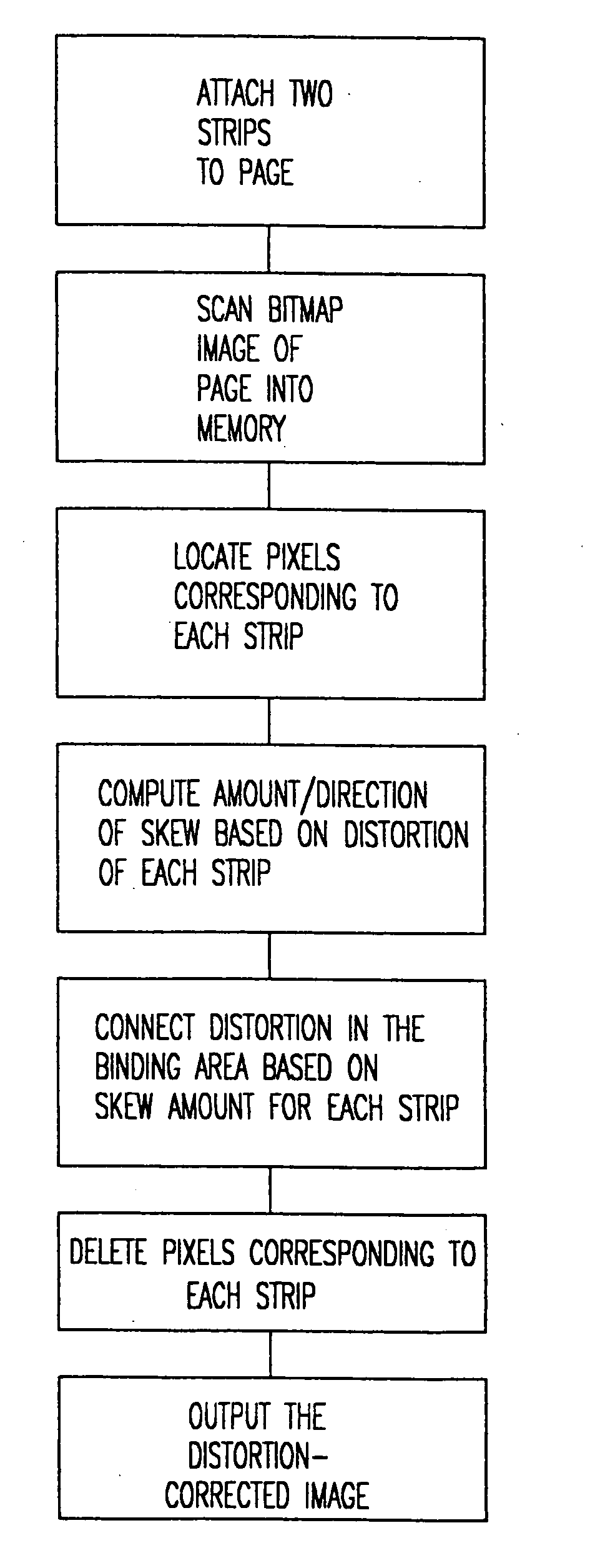
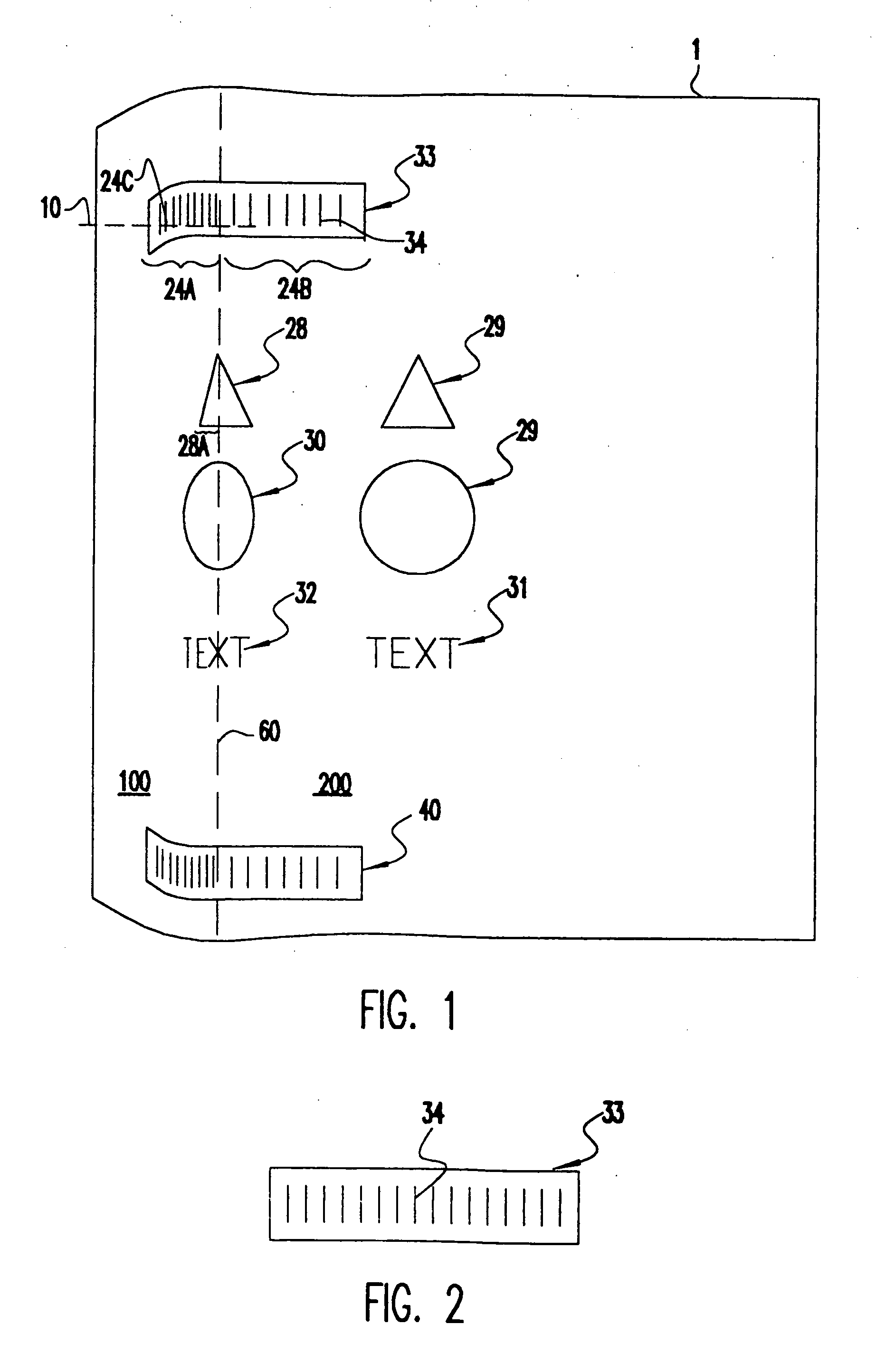
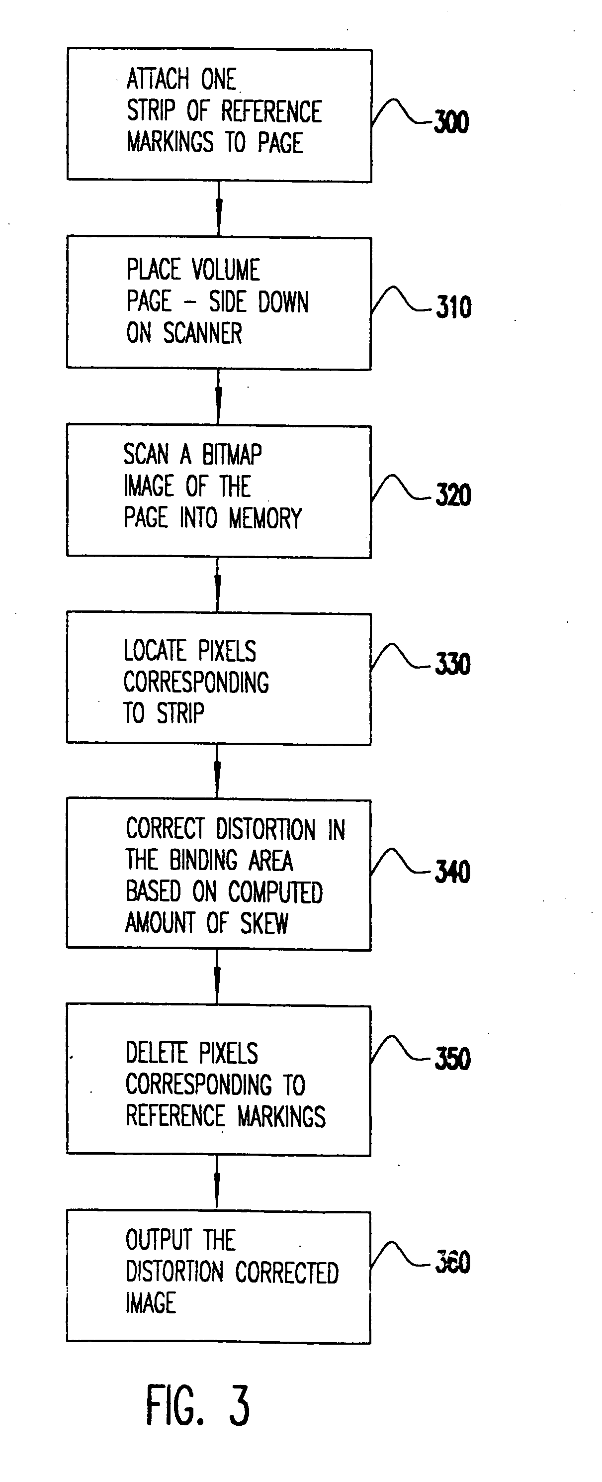
[0029] The present invention is, in one respect, a method for correcting distortion in an image of a document with one or more curved areas which have been optically scanned by a copy machine, facsimile machine, personal computer scanner, or any other type of digital imaging device. The method is particularly well suited to correcting three-dimensional skew effects in images of pages taken from a book, magazine, journal, or other bound volume of substantial thickness; however, those skilled in the art can appreciate that the invention may be applied to a book of any size or even a single page which has curves along its sides or even in its interior portions that occurred, for example, as a result of bending, folding, or warping. The present invention is, in a second respect, a digital imaging device incorporating a processing unit that implements the method of the present invention.

[0030] Turning now to the specific embodiments, a page I of a book viewed two-dimensionally (e.g., in...


PUM


Abstract

Pages of books are copied without distortion due to curvature of the page near the book binding or the distortion in a copied page is corrected using the spacing of equidistant bars on tape strips applied to the top and bottom edges of a page before copying. The tape is preferably transparent and rather narrow and easily attached to a page to be copied. The first step in the distortion correction procedure is to locate the bars at the top and bottom of the page. The distortion of the spacing between the imaged bars is computed based on the known distance between the equidistant bars. The computed distortion of the spacing is then input to a distortion correction algorithm. The output of the distortion correction algorithm generates a corrected image. This image may also optionally delete the bars so that they are not printed in the copy. The corrected image is then copied.

Description

BACKGROUND OF THE INVENTION [0001] 1. Field of the Invention [0002] The present invention generally relates to improving the quality of copies produced by a document imaging device, and more particularly to a method and apparatus for correcting distortions in copies of pages of a book, journal, or other bound volume. [0003] 2. Background Description [0004] Conventional digital copy machines produce copies of pages from a bound volume which are often distorted in the area near the binding. This is because the binding prevents the pages from lying flat against the document glass. More specifically, when a book is opened and a page is placed on the glass, the area of the page near the binding curves away (or upwardly) from the glass surface. As a result, printed information (e.g., text, graphics, etc.) near the binding tends to skew when viewed two-dimensionally by the imaging sensors of the machine. If left uncorrected, the skew will transfer as distortion in the output copy. [0005] I...

Claims


Application Information

Patent Timeline
Patent Type & Authority Applications(United States)
IPC IPC(8): G06K9/03G06K9/32G06K9/78G06K15/00G06T5/00H04N1/409
CPCG06K9/3283H04N1/00002H04N1/00045H04N2201/0434H04N1/00082H04N1/00087H04N1/00092H04N1/0005G06V30/1478
Inventor BRAUDAWAY, GORDON W.GIORDANO, FRANK P.MARTENS, MARCOTRESSER, CHARLES P.WU, CHAI WAHMICCHELLI, CHARLES A.
Owner INT BUSINESS MASCH CORP
Why Eureka
Try Eureka