Objective lens and optical pickup apparatus

a pickup apparatus and optical technology, applied in the field of objective lenses and optical pickup apparatus, can solve the problems of reducing a bigger problem, and achieve the effect of preventing surface deformation and improving the abrasion resistance of the anti-reflection film

Inactive Publication Date: 2005-10-13
KONICA MINOLTA OPTO
View PDF1 Cites 15 Cited by
  • Summary
  • Abstract
  • Description
  • Claims
  • Application Information

AI Technical Summary

Benefits of technology

[0007] An object of the present invention is to improve abrasion resistance of an antireflection film and to prevent deformation of surface of an objective lens which transmits blue light of a short wavelength range of 350 to 450 nm.

Problems solved by technology

However, an objective lens having a high refractive index antireflection film on a lens body made of a resin tends to have a problem in that the lens surface facing to an optical information recording medium is deformed or abrasion resistance of the antireflection film decreases due to a local heat generated at the surface and subsequently conveyed to the lens body, the local heat being generated when the antireflection film absorbs the energy of light at the surface facing to the optical information recording medium side surface.
This may be a bigger problem for an antireflection film having an refractive index of 1.7 or more.

Method used


Image

  • Objective lens and optical pickup apparatus
  • Objective lens and optical pickup apparatus
  • Objective lens and optical pickup apparatus

Examples


example 1

[0341] In this example 1, 30 samples aimed for an objective lens are prepared and the characteristics or properties of prepared samples 1-30 each were measured and evaluated.

(1) Preparation of Samples 1-30

(1-1) Preparation of Lens body

[0342] First, an arbitrary one type of resin was manufactured according to the following manufacturing method of (1-1-1) and (1-1-2) as “resin containing a polymer provided with an alicyclic structure” constituting a lens body. Wherein, “part(s)” and “%” in following (1-1-1) and (1-1-2) are based on weight unless otherwise mentioned.

(1-1-1) Manufacturing Method of Polymer

[0343] Unhydrated cyclohexane of 320 parts, 60 parts of styrene and 0.38 part of dibutyl ether were charged in a stainless steal polymerization vessel equipped with a stirrer and a polymerization reaction was started by addition of 0.36 part of n-butyl lithium solution (a 15% content hexane solution) while stirring. After the polymerization reaction was performed for 1 hour, 20...

example 2

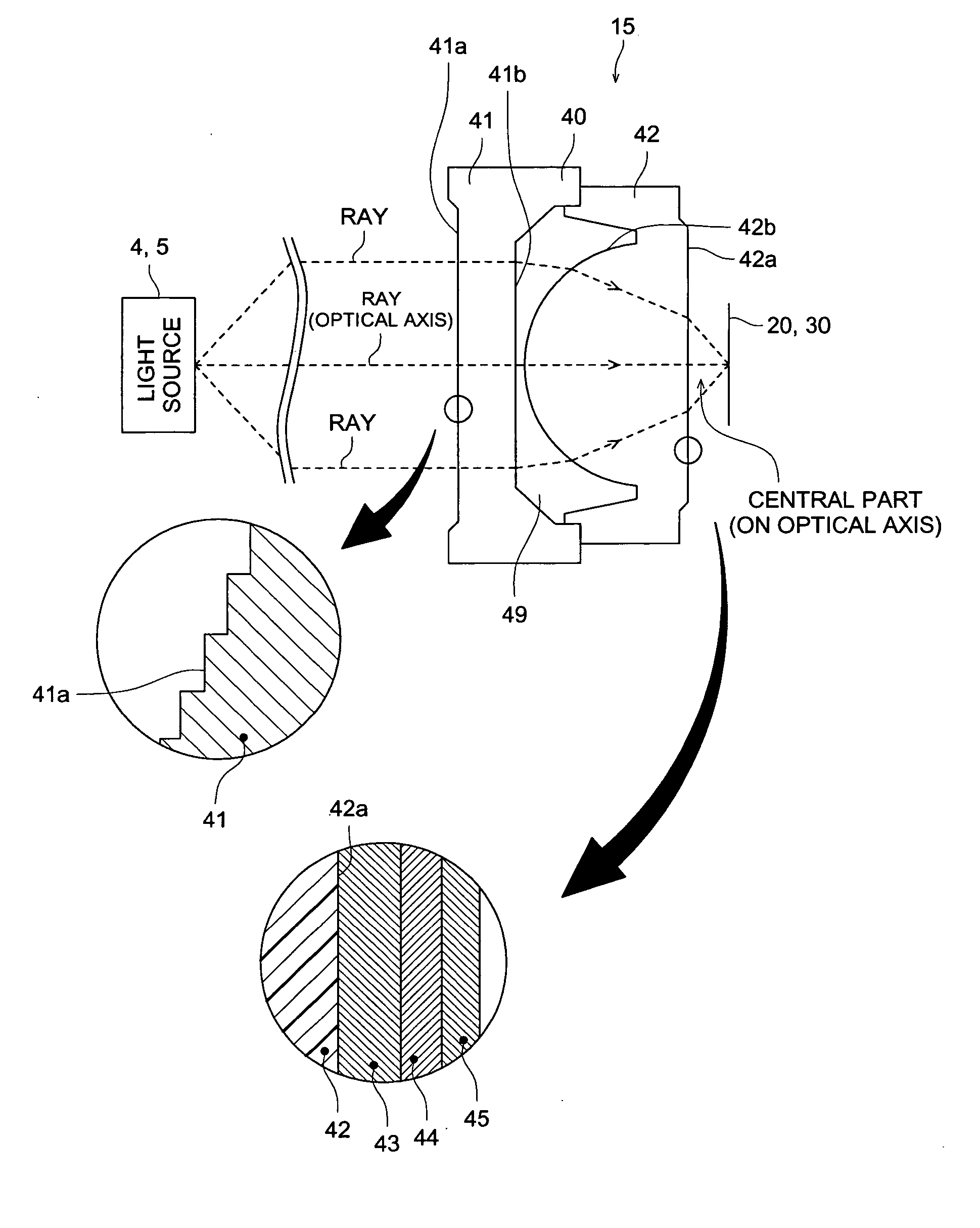
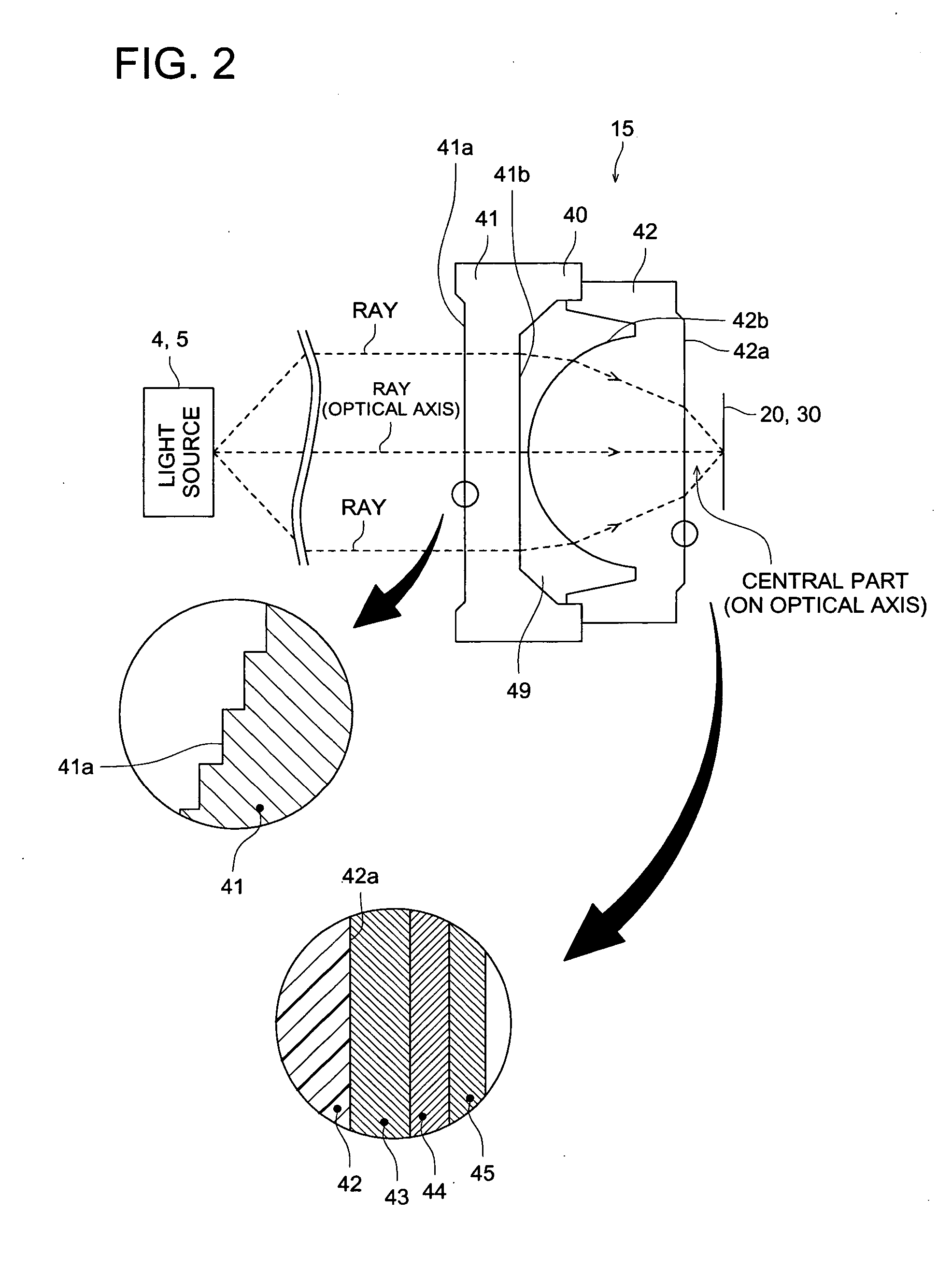
[0393] In example 2, a plural number of samples were prepared utilizing a lens body corresponding to each lens body 40, 50 and 60 shown in FIGS. 2, 3 and 4, and characteristics or properties of each sample prepared were measured and evaluated.

(3) Preparation of Samples 41-54

(3-1) Preparation of Lens bodys A, B and C

(3-1-1) Preparation of Lens body A

[0394] A lens body corresponding to lens body 40 of FIG. 2 was prepared according to the manufacturing method described in items (1-1-1) and (1-1-2) of example 1 above described, and was designated as lens body A. Lens characteristics of lens body A are shown in Table 7. With respect to the lens characteristics of lens body A, for light of wavelength 405 nm, NA=0.85, P1=0, |P1 / P2|=0, d2 / f2=1.31 and f2=2.2 mm, where “NA” represents the numerical aperture on the image side of an optical element corresponding to optical element 42 of FIG. 2, “P1” represents the paraxial power of the optical element corresponding to optical element 41,...


PUM

PropertyMeasurementUnit
specific wavelengthaaaaaaaaaa
refractive indexaaaaaaaaaa

Abstract

An objective lens for converging a monochromatic light flux having a specific wavelength in a range of 350 to 450 nm on an optical information recording medium while the objective lens is placed facing the optical information recording medium, the objective lens comprising: a lens body containing a polymer resin having an alicyclic structure; a first film having a refractive index of less than 1.7 for light having a wavelength of 405 nm; a second film having a refractive index of 1.7 or more for the light having the wavelength of 405 nm; and a third film having a refractive index of 1.55 or less for the light having the wavelength of 405 nm, wherein: the first film, the second film and the third film are provided on the lens body; the first film is provided between the lens body and the second film; the second film is provided between the first film and the third film; and a thickness of the first film is in a range of 50 to 15000 nm.

Description

[0001] This application is based on Japanese Patent Application No. 2004-113166 filed on Apr. 7, 2004 in Japanese Patent Office, the entire content of which is hereby incorporated by reference. TECHNICAL FIELD [0002] The present invention relates to an objective lens converging a monochromatic light flux having a wavelength of 350 to 450 nm on an optical information recording medium and an optical pickup apparatus equipped with the objective lens. BACKGROUND [0003] In recent years, various sizes of optical elements have been manufactured and put into market, for example, from large size optical elements utilized as such as a telescope lens and a microscope lens to small size optical elements, for example, pickup lenses of such as CD (Compact Disc) and DVD (Digital Video Disc). Specifically, development of an optical pickup lens (an objective lens) applicable to at least one of BD (Blue-ray Disc), CD and DVD has been actively carried out in accordance with a proposal of a standard on...

Claims


Application Information

Patent Timeline
Patent Type & Authority Applications(United States)
IPC IPC(8): G02B1/04G02B1/10G02B13/00G02B1/11G02B3/00G02B13/18G11B7/00G11B7/135G11B7/1372G11B7/1374G11B7/139G11B7/1392
CPCG11B7/1374G11B7/139G11B2007/13727G11B2007/0006G11B7/13922
Inventor OHTA, TATSUONOZAKI, TAKASHI
Owner KONICA MINOLTA OPTO
Why Eureka
Try Eureka