Lighting device for display

a technology display, which is applied in the direction of coupling device connection, instruments, spectales/goggles, etc., can solve the problems of large power consumption, large size of light guiding plate, and difficulty in reducing thickness, so as to improve maintenance and recycling efficiency, the effect of holding the light guiding plate steady and easy removal

Inactive Publication Date: 2005-10-13
SHARP KK
View PDF11 Cites 63 Cited by
  • Summary
  • Abstract
  • Description
  • Claims
  • Application Information

AI Technical Summary

Benefits of technology

[0099] As obvious from the above description, according to the invention, the power supply line is detachably connected to the terminal of the light source via the connector. Therefore, the light source can be removed by being separated from the power supply line and the like when it is failed. This improves the maintenance and recycling efficiencies. Further, since the connector is fitted in the insertion portion of the chassis so as to be held stably, the light source can be easily removed independently by being drawn to be separated from the connector, which improves the operability. Further, since the electrode terminal of the light source and the power supply line are connected by using the connector and without soldering, it is possible to reduce the number of operations and the operational cost for assembling.

Problems solved by technology

However, the vertical type has such demerits as a difficulty in reducing thickness and a large power consumption.
However, the edge light type has such demerits that the size of the light guiding plate becomes larger as the screen size becomes larger, and the weight becomes heavier.
Therefore, in a case of maintenance when the linear light source 1 is failed, it is difficult to remove only the linear light source 1, causing a problem of poor performance in maintenance and recycle.
Further, in manufacturing, there is required an operation of soldering the power supply lines 3 and 4 to the electrode terminals 2A and 2B of the linear light source 1, respectively, causing a problem of increasing the number of operations and operational cost.
However, according to the contact member 6 described in the aforementioned publication, it has conductivity with conductive resin, whereby it is less conductive comparing with a metal, causing an energy loss.
Further, since the contact member 6 is so configured that the conductive members 11 and 14 of the fluorescence tube 9 for backlight and of the power supply line 12 are inserted in the first hole 15 and the second hole 16, respectively, a problem of low reliability in electrical connection is caused.
Moreover, since the contact member 6, the fluorescence tube 9 for backlight, and the power supply line 12 are not fixed, a problem of low reliability in positioning and holding is caused.
Thereby, a high luminance area H and a low luminance area G are generated due to a difference in the current densities of the HOT side and the GND side, causing a problem of luminance nonuniformity in the axial direction of the linear light sources 1.
Further, when a current supplied to each linear light source 1 has the same phase, flickers of adjacent linear light sources 1 are in the same frequency, causing a problem that flickers of the backlight as a whole are increased and electrical noises are caused to the liquid crystal panel.

Method used


Image

  • Lighting device for display
  • Lighting device for display
  • Lighting device for display

Examples


first embodiment

[0159] FIGS. 1 to 5 show a

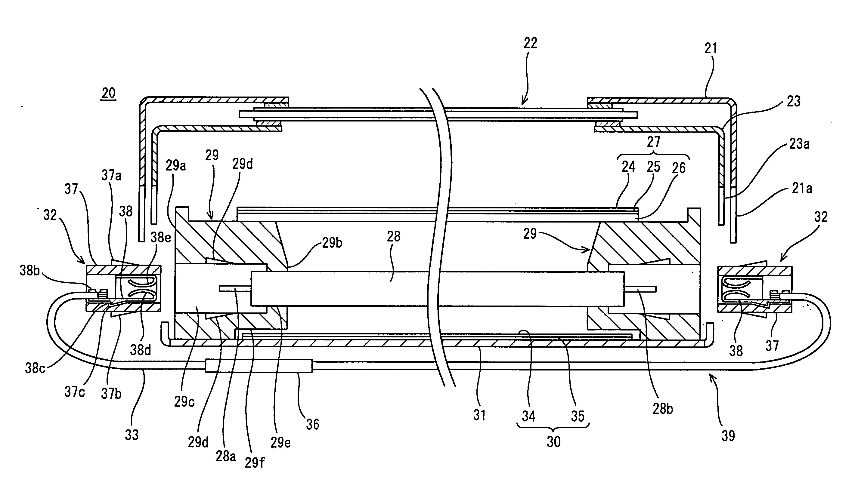
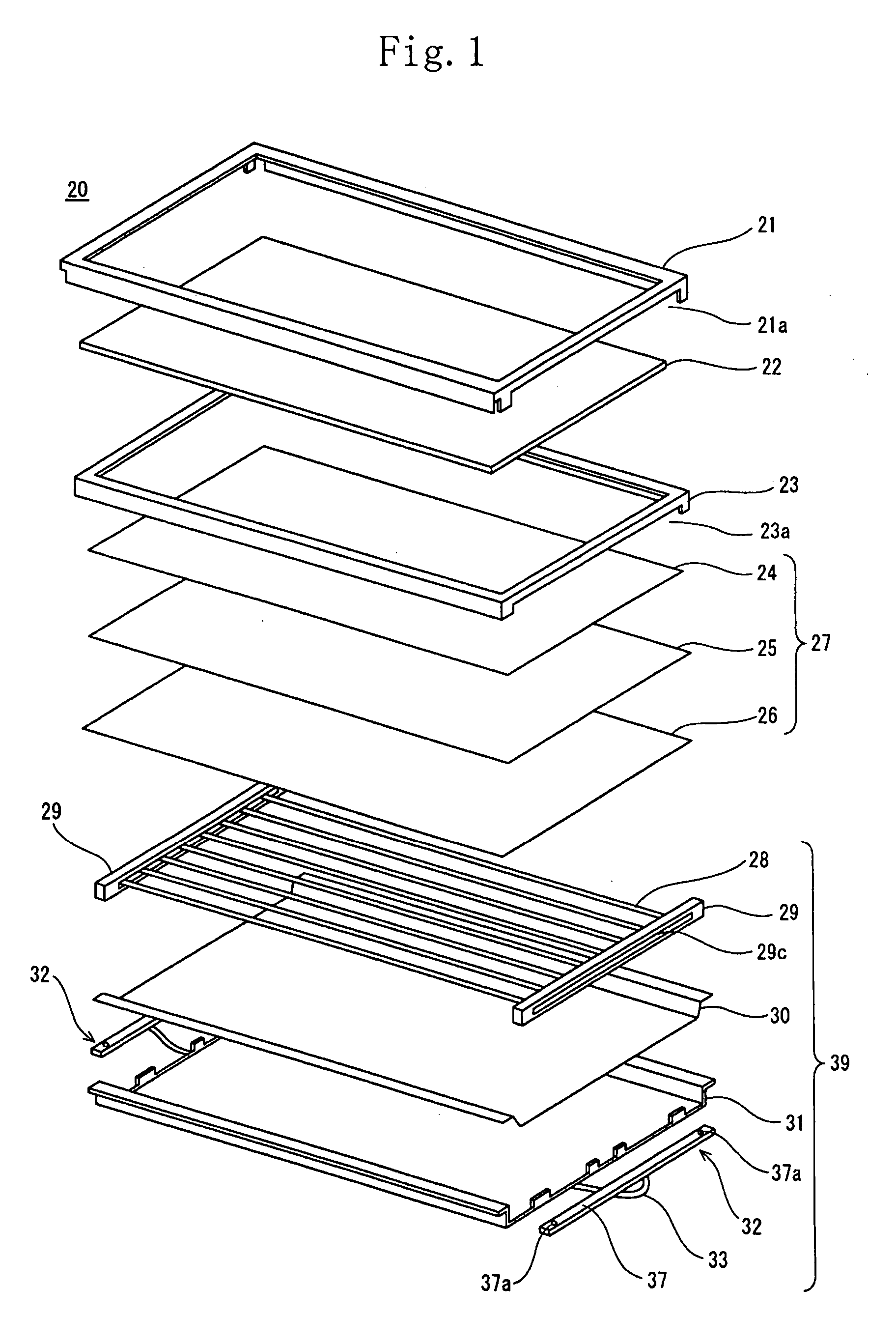
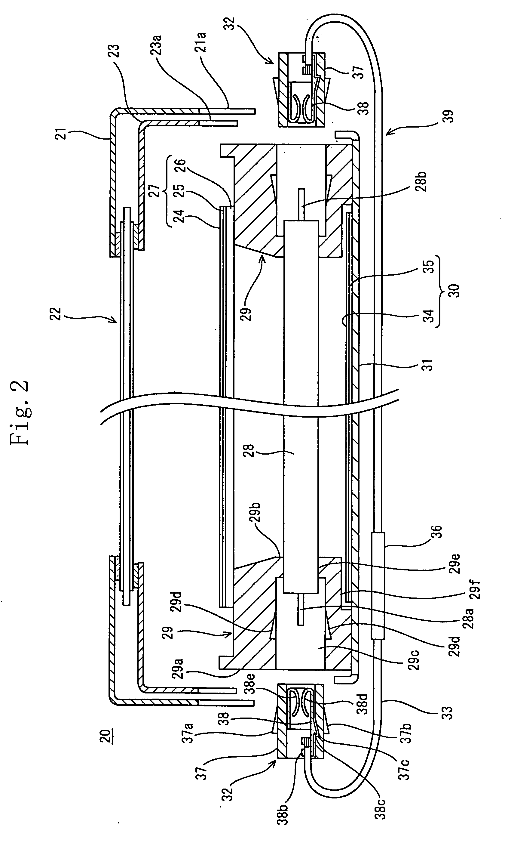
[0160] A display of this embodiment is a liquid crystal display 20, in which the peripheral edges of a liquid crystal panel 22 are held in between a frame-shaped front chassis 23 and a bezel 21, and an optical sheet group 27, which is an optical member, is placed under the liquid crystal panel 22. Under the optical sheet group 27, a plurality of linear light sources 28 are arranged in parallel, and the ends 28a and 28b of each linear light source 28 are held by light source-holding chassis 29. In such a state, the liquid crystal display 20 is closed from the bottom with a reflecting composite member 30 and a back chassis 31. To the end of a power supply line 33 connected to an inverter 36 disposed on the rear face side of the back chassis 31, a connector 32 is connected. This connector 32 is inserted and inwardly fitted in an insertion portion 20c of the light source-holding chassis 29 to thereby supply power to the linear light sources 28.

[0161] As the li...

second embodiment

[0174]FIGS. 6A and 6B show a

[0175] In this embodiment, a connector 40 and a power supply line 33 are detachable. That is, the end of the power supply line 33 is connected to a small connector 43 which is inwardly fitted in and locked to a mounting hole 41f of the connector 40.

[0176] The housing 41 of the connector 40 is provided with locking portions 41a and 41b on the upper and lower outer faces thereof, and a concave portion 41c in the inner face thereof. The backward side forms the mounting hole 41f for the small connector 43, and a to-be-locked portion 41d is provided on the inner face of the mounting hole 41f. A press-contact terminal 42 has, on a part of the back end side of the substrate 42a, a press-contact tub 42b in which a slot 42c is cut out, and has a pair of elastic tongue pieces 42d and 42e formed by being folded from the front end side of the substrate 42a, to be face-to-face in an inverted U-shape. The pair of elastic tongue pieces 42d and 42e are provided in plura...

third embodiment

[0179]FIG. 7 shows a

[0180] In this embodiment, a number of connectors 48, connected to the power supply line 33, are provided corresponding to the number of linear light sources 28 so as to be provided one by one.

[0181] A light source-holding chassis 47 has a number of insertion portions 47a perforated corresponding to the number of linear light sources 28. Each connector 48 is inserted and inwardly fitted in an insertion portion 47a so that a locking portion 48a is locked and fixed to a to-be-locked portion (not shown) in the inner face of the insertion portion 47a. Other configurations are similar to those of the first embodiment, so their explanations are omitted.


PUM

PropertyMeasurementUnit
reflectivityaaaaaaaaaa
areaaaaaaaaaaa
U-shapeaaaaaaaaaa

Abstract

An object of the invention is to make a light source and a power supply line detachable easily so as to enable the light source to be replaced easily for maintenance. The invention provides a lighting device for a display, which includes a light source having electrode terminals provided at both ends thereof, connectors attached to the ends of a power supply line for supplying power to the light source, light source-holding chassis placed at the ends of the light source, and insertion portions opened in the chassis. The electrode terminals of the light source are placed inside the insertion portions, and the connectors are fitted detachably in the insertion portions from the outside, whereby the terminals in the connectors are connected to the electrode terminals.

Description

[0001] This nonprovisional application claims priority under 35 U.S.C. § 119(a) on Patent Application No(s). 2004-117295 filed in Japan on Apr. 12, 2004, the entire contents of which are hereby incorporated by reference. BACKGROUND OF THE INVENTION [0002] 1. Field of the Invention [0003] The invention relates to a lighting device for a display, and in particular, to a lighting device used for a display in which a light source constituting the lighting device is supplied with power from a power supply line. [0004] 2. Description of the Related Art [0005] In recent years, a display called FPD (Flat Panel Display), which is thin and flat, has been developing a larger market comparing with a display in which a CRT (Cathode Ray Tube) is used. Among various types of FPDs, plasma displays and liquid crystal displays are the mainstream. Both have characteristics, respectively. A plasma display utilizes a discharge phenomenon so as to enable a large screen and high luminance. On the other ha...

Claims


Application Information

Patent Timeline
Patent Type & Authority Applications(United States)
IPC IPC(8): G02F1/1333F21S2/00F21V5/00F21V8/00F21V17/00F21Y101/02F21Y103/00G02F1/13357H01R33/02H01R33/08
CPCG02F2001/133612G02F1/133604G02F1/133612G02C5/12G02C2200/02
Inventor AOKI, KENTAROHIWAMOTO, KENICHITAKATA, YOSHIKI
Owner SHARP KK
Why Eureka
Try Eureka