Water-cooler radiator module

a radiator module and water-cooling technology, applied in the direction of instruments, lighting and heating apparatus, and semiconductor/solid-state device details, can solve the problems of reducing the possibility of any damage to the heat-generating electronic component, reducing the weight of the generating electronic component, and saving space. , to achieve the effect of more stable installation of the shell body

Inactive Publication Date: 2005-10-20
ADDA
View PDF7 Cites 31 Cited by
  • Summary
  • Abstract
  • Description
  • Claims
  • Application Information

AI Technical Summary

Benefits of technology

[0008] It is therefore a primary object of the invention to provide a water-cool radiator module that comprises a supporting part that further comprises a shell body; the shell body comprises a fan and a water tank; the water tank is connected to a cold water pipe and a hot water pipe; the extended section of the cold water pipe and hot water pipe connects to a cold waterhead; the shell body further comprises several radiating holes at one end; in practical application, the supporting part is fixed in a slot on the computer case and the shell body is firmly fixed on the slot; cold water on heat-generating electronic component is sent to the shell body via hot the water pipe; blown by the fan, heat is radiated outward via radiating holes; and cool fluid flows from the water tank to the cold waterhead via the cold water pipe. With repeated circulation, the heat produced by electronic component is taken away quickly. On the other hand, since the water tank, the radiating fins and the fan are all fixed on slot, the heat-generating electronic component does not bear the weight of the water tank, the radiating fins and the fan. As a result, this reduces the possibility of any damage to the heat-generating electronic component and saves space above the heat-generating electronic component.
[0009] It is still an object for the invention to provide a water-cool radiator module in which a pump is installed inside the shell body to speed up the flow of hot water in the hot water pipe and control the flow direction.

Problems solved by technology

On the other hand, since the water tank, the radiating fins and the fan are all fixed on slot, the heat-generating electronic component does not bear the weight of the water tank, the radiating fins and the fan.
As a result, this reduces the possibility of any damage to the heat-generating electronic component and saves space above the heat-generating electronic component.

Method used


Image

  • Water-cooler radiator module
  • Water-cooler radiator module
  • Water-cooler radiator module

Examples


Embodiment Construction

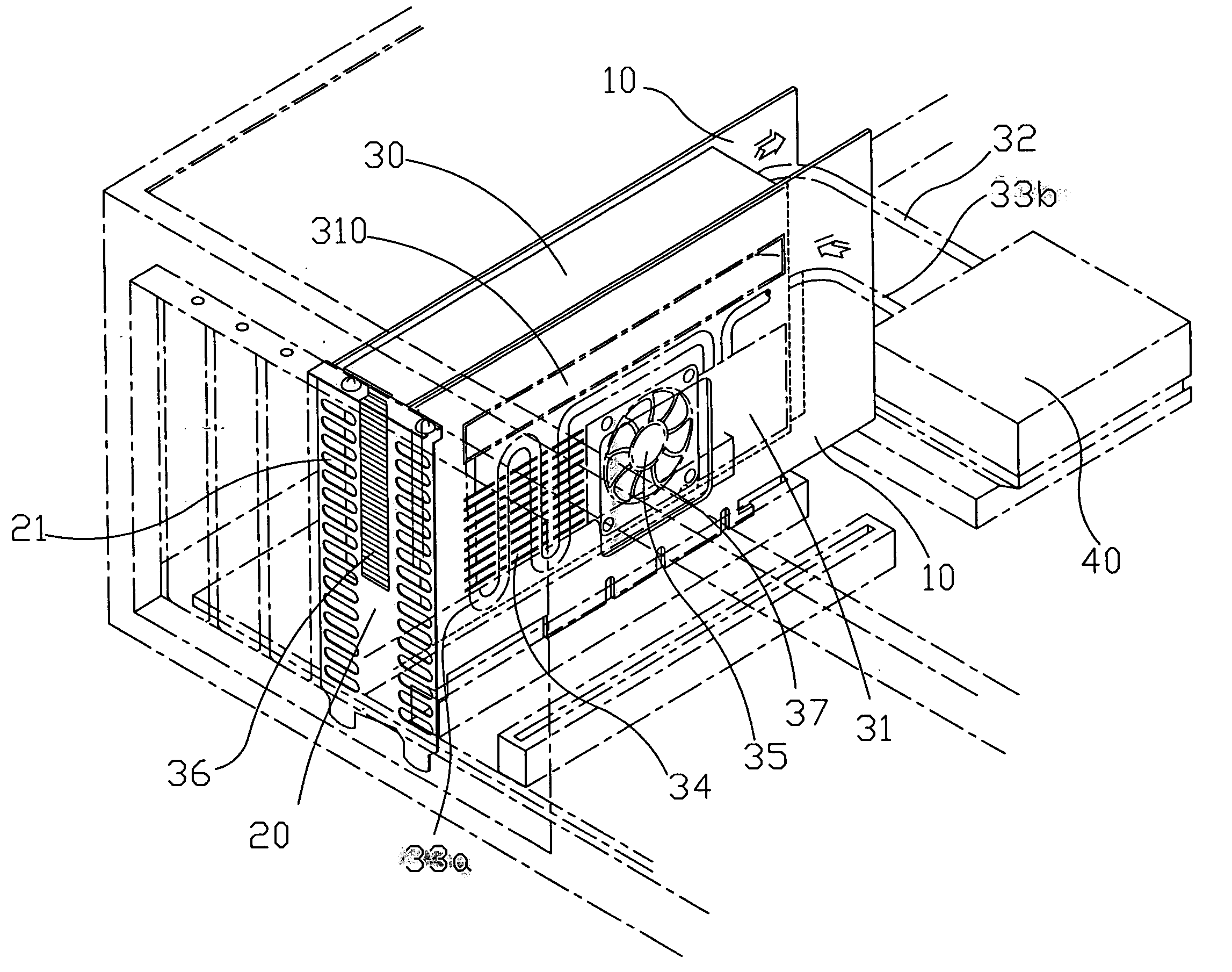
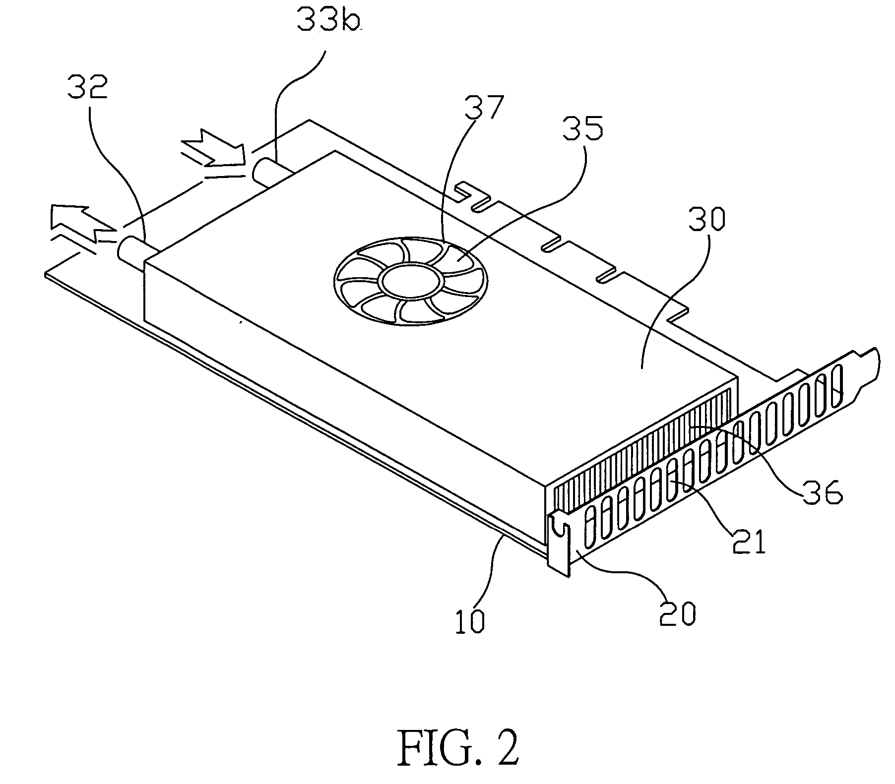
[0017]FIG. 2 shows a preferred embodiment of the water-cool radiator module in the present invention wherein the module comprises a supporting part 10, a supporting part 10 can couple with the interfaces of various types of extended slots such as AGP, PCI and ISA on one side, the supporting part 10 comprises a fixing part 20 on the other side; the fixing part 20 is perpendicular to supporting part 10 and comprises holes 21.

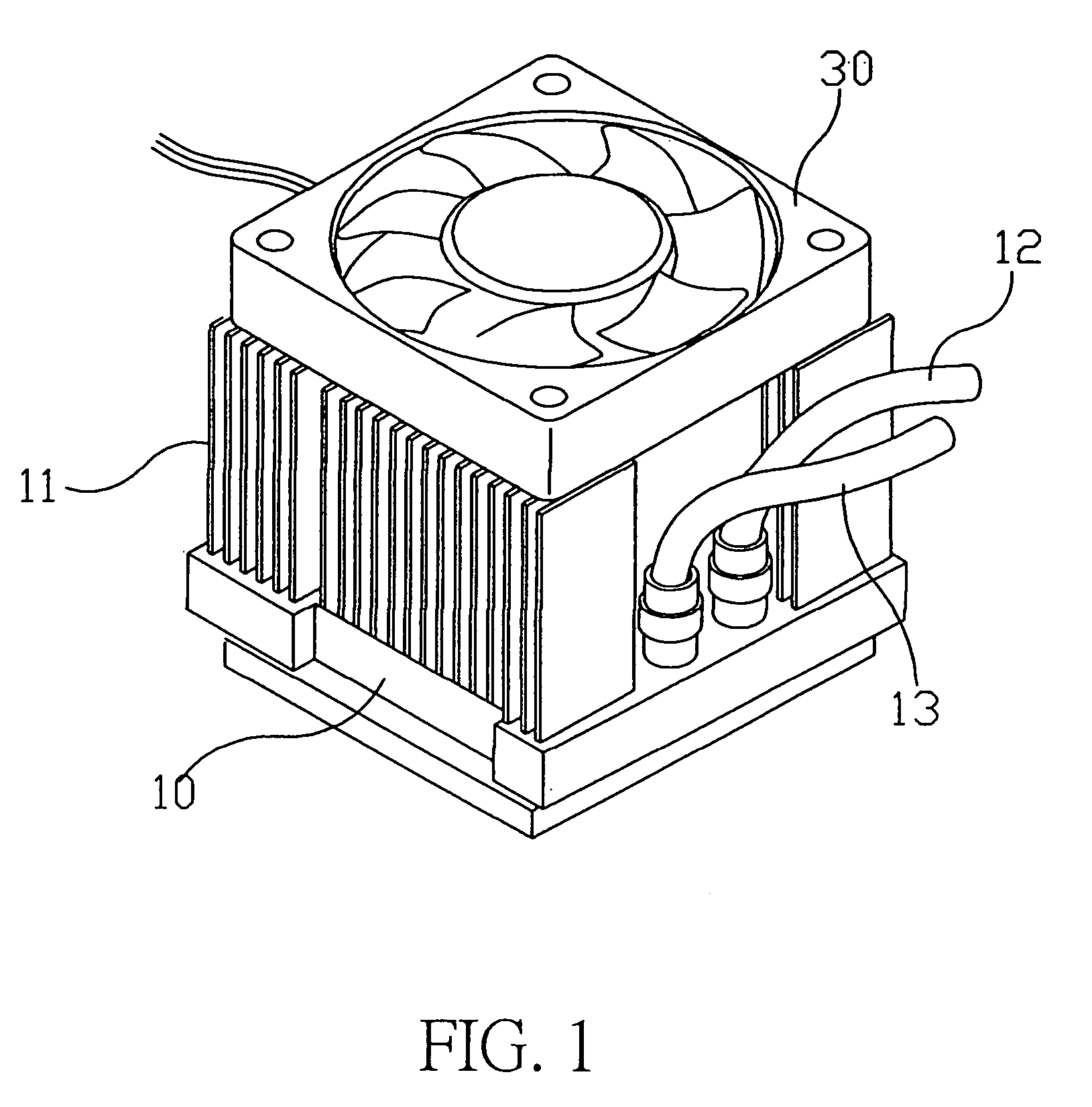
[0018] As shown in FIG. 3, the supporting part 10 comprises a shell body 30; the shell body 30 comprises a water tank 310 which connects to a cold water pipe 32 and a hot water pipe 33 on the other side; several radiating fins 34 are aligned orderly on the bending section of the hot water pipe 33; a fan 35 is located adjacent to the radiating fins 34; an opening 37 is located at a region where the shell body 30 is not braced against the supporting part 10; the opening 37 faces the fan 35; a pump 31 is located beside the fan 35 and connected to the hot water pipe ...


PUM


Abstract

A water-cool radiator module comes with a supporting part having a shell body; the shell body includes a fan and a water tank; the water tank is connected to a cold water pipe and a hot water pipe; an extended section of the cold water pipe and hot water pipe is connected to a cold waterhead; the shell body includes several radiating holes at one end; such that in an application, the supporting part is inserted into a slot on the computer case and the shell body is mounted onto the slot; the cold water in the cold waterhead of a heat-generating electronic component is circulated to the shell body through the hot water pipe; the fan blows air to radiate heat to the outside through the radiating holes; and the cooled fluid flows from the water tank to the cold waterhead through the cold water pipe.

Description

BACKGROUND OF THE INVENTION [0001] 1. Field of the Invention [0002] The present invention relates generally to a radiator module and, more specifically, a water-cool radiator module that is separated from heavy water tank, cold water pipe and hot water pipe that are independently fixed in a slot for the purpose to reduce the load on the heat-generating electronic components and not occupy the space of the electronic components. [0003] 2. Description of the Prior Art [0004] Heretofore, it is known that a conventional radiator. As shown in FIG. 1, generally comprises a flat pedestal 10 that comprises a plurality of radiating fins 11 and a water conduit (not shown in Fig.) on the other side; the water conduit comprises a water inlet 12 and a water outlet 13; the pedestal 10 further comprises a fan 30. In practical use, this configuration has the following disadvantages: [0005] 1. In addition to radiating fins 11, some water conduit accessories are also located under radiating fins 11. ...

Claims


Application Information

Patent Timeline
Patent Type & Authority Applications(United States)
IPC IPC(8): F28D1/02F28D1/047F28F7/00G06F1/20H01L23/473H05K7/20
CPCF28D1/024F28D1/0477G06F1/20G06F2200/201H01L2924/0002H01L23/473H01L2924/00
Inventor HSIEH, HSIN MAO
Owner ADDA
Why Eureka
Try Eureka