Cylindrical fluid-filled vibration damping device

a technology cylindrical fluid, which is applied in the direction of shock absorber, jet propulsion mounting, machine support, etc., can solve the problems of insufficient filling of vibration damping device, easy slippage of stick, and discomfort of passengers in the vehicle, and achieves smooth performance, high efficiency, and high durability of the elastic body striking portion

Inactive Publication Date: 2005-10-20
SUMITOMO RIKO CO LTD
View PDF7 Cites 18 Cited by
  • Summary
  • Abstract
  • Description
  • Claims
  • Application Information

AI Technical Summary

Benefits of technology

[0009] It is therefore an object of the present invention to resolve the problems discussed above and provide a cylindrical fluid-filled vibration-damping device which suppresses the occurrence of stick slip due to friction between the inner circumferential surface of the outer cylindrical sleeve and the stopper member, and is able to prevent effectively the accompanying noise when the stopper member strongly strikes the inner circumferential surface of the outer cylindrical sleeve due to excessive vibrational input.
[0012] In the invention with the above constitution, when vibration is input between the inner cylindrical sleeve and the outer cylindrical sleeve due to vibration of the engine or the like, that vibration can be damped by the elastic action of the rubber elastic body and the resonance of the fluid column of the fluid flowing through the orifice passage between the primary fluid chamber and auxiliary fluid chamber. Furthermore, the provision of the elastic body striking portion on the inner circumferential surface of the outer cylindrical sleeve, which is formed of the self-lubricating rubber and having a low coefficient of friction with respect to the tip of the stopper member, suppresses the occurrence of stick slip, resulting from friction between the inner circumferential surface of the outer cylindrical sleeve and the tip of the stopper member when the vibrational input becomes excessive and the stopper member strongly strikes the inner circumferential surface of the outer cylindrical sleeve. For this reason, the present invention can effectively prevent the occurrence of the noise accompanying stick slip. The use of the self-lubricating rubber within the sealed fluid makes it possible for the fluid-filled vibration-damping device to enhance effect of preventing occurrence of the stick slip, and to provide the enhanced stick slip preventing effect for a long period of time.
[0013] A second mode of the invention provides a cylindrical fluid-filled vibration-damping device according to the first mode, further comprising: an arcuate plate shaped mounting member mounted on an outside of the connecting portion, extending circumferentially along the inner circumferential surface of the outer cylindrical sleeve and facing the recessed portion, while engaging with the connecting portion with both circumferential end portions, wherein the elastic body striking portion is adhered to an inner circumferential surface of the mounting member. With this arrangement, since the elastic body striking portion is adhered on the inner circumferential surface of the outer cylindrical sleeve between the pair of ring portions, the abovementioned effective action of the invention is attained and it becomes unnecessary to position the elastic body striking portion when the outer cylindrical sleeve is attached on the outside of the intermediate sleeve and the labor for that purpose is saved. Furthermore, in the case when the rubber seal portion is provided on the outer surface of the ring portions, it is possible to avoid direct contact between the elastic body striking portion with the low coefficient of friction and the rubber seal portion for ensuring the seal between the intermediate sleeve and the outer cylindrical sleeve. For this reason, in the present invention, the junction between the outer cylindrical sleeve and the intermediate sleeve with the rubber seal portion therebetween can be maintained securely and the loosening of the outer cylindrical sleeve is prevented with certainty.
[0015] With this arrangement, the mounting member with the elastic body striking portion adhered on the inner circumferential surface thereof, faces the recessed portion opening towards the outer cylindrical sleeve and surrounded by the pair of sidewall portions and the arm portion, extends circumferentially along the inner circumferential surface of the outer cylindrical sleeve, engages at circumferential edge portions thereof with the connecting portion, and are mounted on the outside of the connecting portion. The elastic body striking portion is disposed opposite to the stopper member. For this reason, in the present invention, when the stopper member strongly strikes the inner circumferential surface of the mounting member due to excessive vibrational input, the occurrence of stick slip from friction between the inner circumferential surface of the mounting member and the stopper member because of the elastic body striking portion is suppressed, and the occurrence of the accompanying noise is effectively prevented. Also, since the elastic body striking portion is formed on the mounting member and separately from the outer cylindrical sleeve, the inlay of the outer cylindrical sleeve on the intermediate sleeve can be performed smoothly without being obstructed by the elastic body striking portion.
[0016] A fourth mode of the invention provides a cylindrical fluid-filled vibration-damping device according to any one of the first through third modes, wherein the stopper member is formed of a rigid material and coated with a rubber layer, and opposite to the elastic body striking portion of self-lubricating rubber with a spacing therebetween. With this arrangement, upon application of an excess load, the rigid stopper member is brought into abutting contact with the self-lubricating rubber via a rubber layer, whereby the occurrence of stick slip can be eliminated with high efficiency, and a high durability of the elastic body striking portion of self-lubricating rubber. In other words, the combination use of the rigid stopper member, the rubber layer coating the rigid stopper and the elastic body striking portion of the self-lubricating rubber makes it possible to assure all of an excellent stopper function of the stopper member, a prevention of impact noises, and a durability of the self-lubricating rubber, in addition to an excellent elimination of occurrence of stick slips of the stopper member.
[0017] With the present invention, an elastic body striking portion of self-lubricating rubber is established integrally with the outer cylindrical sleeve or integrally with a mounting member which is separate from the outer cylindrical sleeve on the inner circumferential surface of the outer cylindrical sleeve, and opposite to the tip of the stopper member projecting from the inner cylindrical sleeve. Thereby is suppressed the occurrence of stick slip due to friction between the stopper member and the inner circumferential surface of the outer cylindrical sleeve when the stopper member strongly strikes the inner circumferential surface of the outer cylindrical sleeve due to excessive vibrational input. As a result, in the present invention, noise accompanying stick slip can be effectively prevented and the ride quality of the vehicle can be improved by the elimination of discomfort to passengers in the vehicle. Also, in the present invention, when a rubber seal portion is established on the outer surface of the ring portion, an elastic body striking portion of self-lubricating rubber with a low coefficient of friction is established on the inner circumferential surface of the outer cylindrical sleeve between the pair of ring portions. Therefore, direct contact between the elastic body striking portion and the rubber seal portion can be avoided and the junction between the ring portions of the outer cylindrical sleeve with the rubber seal portion interposed therebetween is securely maintained. Accordingly, with the present invention, the reliability of the cylindrical fluid-filled vibration-vibration-damping device is improved and the loosening of the outer cylindrical sleeve from the intermediate sleeve is prevented.

Problems solved by technology

At the time of the abovementioned excessive vibrational input, stick slip occurs easily because of the tip side firmly striking and grinding against the metal surface of the outer cylindrical sleeve.
A problem is that noise generated along with this stick slip causes discomfort to passengers in the vehicle.
However, the aforementioned cylindrical fluid-filled vibration-damping devices are not necessarily sufficient to suppress stick slip because of the magnitude of the principal vibrational input and it is necessary to further suppress noise within the vehicle in order to improve the ride quality of the vehicle.

Method used


Image

  • Cylindrical fluid-filled vibration damping device
  • Cylindrical fluid-filled vibration damping device
  • Cylindrical fluid-filled vibration damping device

Examples


first embodiment

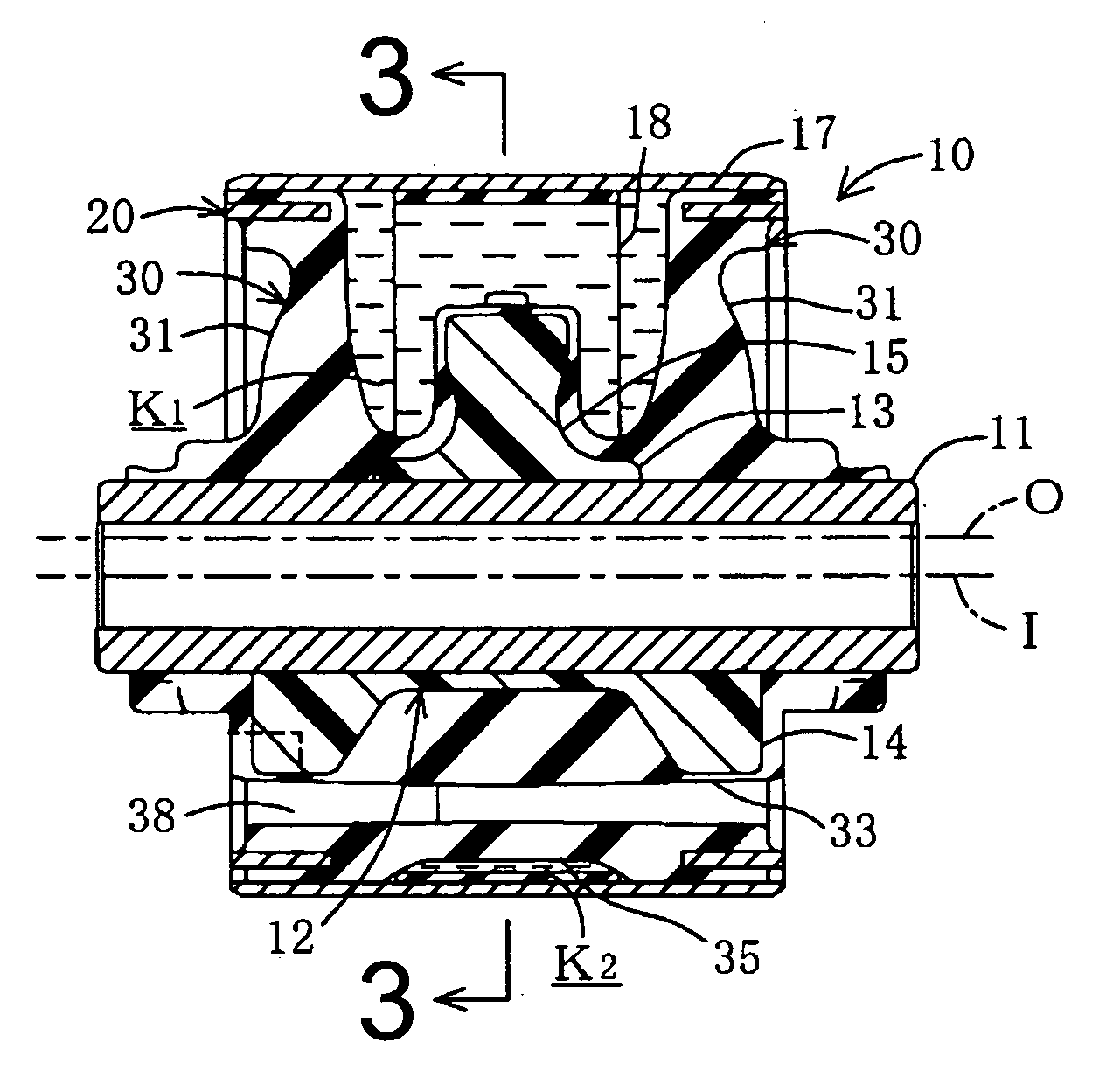
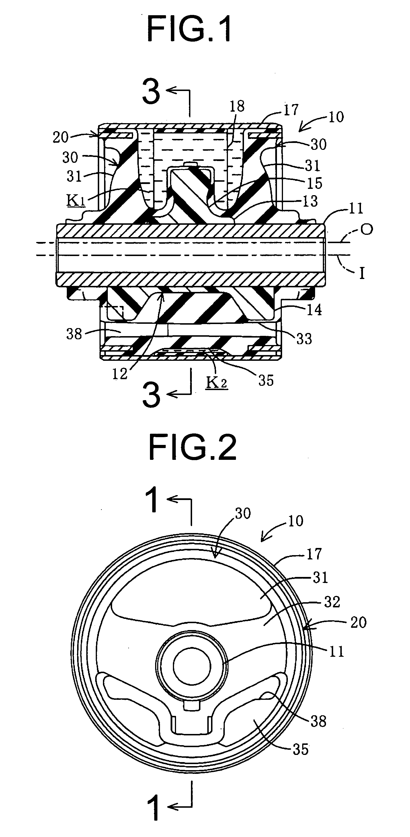
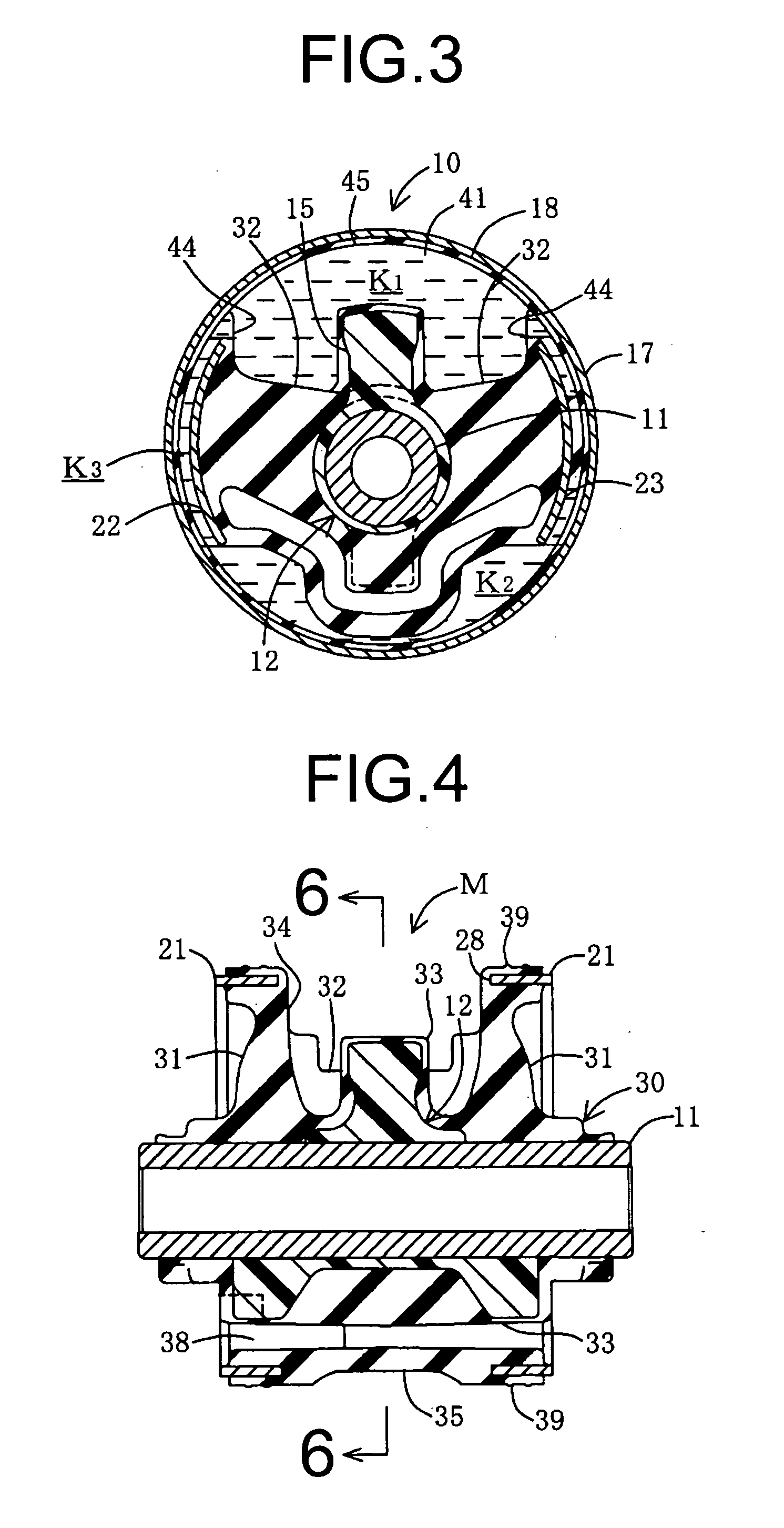
[0041] The abovementioned vulcanized rubber molded product M and the outer cylindrical sleeve 17 are immersed in a tank filled with a non-compressible fluid such as water, alkylene glycol, or the like. The outer cylindrical sleeve 17 is placed coaxially on the outside of the intermediate sleeve 20 of the vulcanized rubber molded product M, and the passage-forming recessed portion 26a, recessed portion 34, and curved recessed portion 37 are filled with fluid. Furthermore, with the constriction of the outside of the outer cylindrical sleeve 17 through a drawing operation, the outer cylindrical sleeve 17 compresses the rubber seal portion 39 adhered on the outside of the ring portions 21 and is attached in a compressed state on the outside of the vulcanized rubber molded product M. The fluid-filled vibration-damping device 10 of construction is thereby attained. Thereby, the opening side of the recessed portion 34 of the rubber elastic body 30 is occluded in a fluid tight manner and f...

second embodiment

[0051] With the second embodiment with the above constitution, when vibration is input between the inner cylindrical sleeve 11 and outer cylindrical sleeves 17 due to the vibration of the engine or the like, that vibration is damped by the elastic action of the rubber elastic body for 30 and by the resonance action of the fluid column of the fluid flowing between the primary fluid chamber K1 and auxiliary fluid chamber K2 through the orifice passage K3. Also, when excess vibration in the bound direction is input between the inner cylindrical sleeve 11 and outer cylindrical sleeve 17, the upward projecting portion 15 of the stopper member 12 strikes the elastic body striking portion 46 disposed on the inner circumferential surface of the mounting member 40 pressed against the outer cylindrical sleeve 17. When excess vibration in the rebound direction is applied, the displacement between the inner cylindrical sleeve 11 and outer cylindrical sleeve 17 is suppressed to within a fixed ra...


PUM


Abstract

A cylindrical fluid-filled vibration-damping device including a rubber elastic body elastically connecting an inner and intermediate cylindrical sleeve having an opening portion defined by ring portions and a connecting portion, and an outer cylindrical sleeve disposed on the intermediate sleeve, thereby forming a primary fluid chamber filled with a fluid inside an recessed portion of the rubber elastic body, an auxiliary fluid chamber filled with the fluid and defined by a diaphragm portion and an orifice passage connecting the primary fluid chamber and auxiliary fluid chamber between itself and the connecting portion. A stopper member disposed on the inner cylindrical sleeve and protruding radially in one direction towards the opening portion of the intermediate cylindrical sleeve, and an elastic body striking portion formed of self-lubricating rubber and having a low coefficient of friction and disposed on an inner circumferential surface side of the outer cylindrical sleeve to be opposite to a tip of the stopper member.

Description

INCORPORATED BY REFERENCE [0001] The disclosure of Japanese Patent Application No. 2004-119588 filed on Apr. 14, 2004 including the specification, drawings and abstract is incorporated herein by reference in its entirety. BACKGROUND OF THE INVENTION [0002] 1. Field of the Invention [0003] The present invention relates to a cylindrical fluid-filled vibration-damping device used as vehicle engine mounts or the like. [0004] 2. Description of the Related Art [0005] A known cylindrical fluid-filled vibration-damping device of this kind includes: an inner cylindrical metal sleeve, and a tubular intermediate metal sleeve as well as an outer cylindrical metal sleeve that are disposed about the inner cylindrical metal sleeve with a radial spacing therebetween. A stopper member is mounted on the outer circumferential surface of the inner sleeve, protruding radially in one direction towards an opening in the intermediate sleeve, with its tip or distal end opposed to the inner circumferential s...

Claims


Application Information

Patent Timeline
Patent Type & Authority Applications(United States)
IPC IPC(8): B62D27/04B60K5/12F16F5/00F16F13/00F16F13/08F16F13/14
CPCF16F13/1418F16F13/1409
Inventor MINAMISAWA, TADAMITSU
Owner SUMITOMO RIKO CO LTD
Why Eureka
Try Eureka