
Charged-particle beam accelerator, particle beam radiation therapy system using the charged-particle beam accelerator, and method of operating the particle beam radiation therapy system

a radiation therapy system and accelerator technology, applied in accelerators, electric discharge tubes, basic electric elements, etc., can solve the problems of system becoming considerably costly, rf-ko is not disclosed in the publication, and the reliability of equipment is not known, so as to achieve efficient irradiation and reduce unwanted dose

Active Publication Date: 2005-10-20
MITSUBISHI ELECTRIC CORP
View PDF6 Cites 111 Cited by
  • Summary
  • Abstract
  • Description
  • Claims
  • Application Information

AI Technical Summary

Benefits of technology

The present invention provides a charged-particle beam accelerator that simplifies beam extraction control, increases reliability, reduces hardware elements, and allows for a wide range of ripples in currents. The accelerator also reduces the cost of operation. Additionally, a particle beam radiation therapy system employing this accelerator and a method of operating it are also provided. The accelerator allows for continuous extraction of the charged-particle beam with a simple control operation, even if there are large ripples in the output of each electromagnet power supply. Overall, the charged-particle beam accelerator reduces system size, improves reliability, and lowers cost.

Problems solved by technology

Although this Patent Publication proposes a beam extraction method for extracting a charged-particle beam from an accelerator by applying a high-frequency electromagnetic field to the circulating beam to increase the amplitude of betatron oscillation, the Publication does not disclose any practical method of frequency control for radio frequency knockout (RF-KO).
This requires a complicated control system which results in an expensive beam radiation system, also causing a problem concerning equipment reliability which is most important for medical systems.
Therefore, optimization of the parameters at construction and adjustment of the charged-particle beam radiation system is so time-consuming that the system becomes considerably costly.
If the stability of the power supply is lowered for the sake of cost reduction, however, resultant fluctuation in power supply voltage will cause limits of a stability region to fluctuate.
Therefore, even if the charged-particle beam radiation system is entirely turned off, a beam will be emitted afterwards due to the power supply voltage fluctuation and this poses a serious problem.

Method used


Image

  • Charged-particle beam accelerator, particle beam radiation therapy system using the charged-particle beam accelerator, and method of operating the particle beam radiation therapy system
  • Charged-particle beam accelerator, particle beam radiation therapy system using the charged-particle beam accelerator, and method of operating the particle beam radiation therapy system
  • Charged-particle beam accelerator, particle beam radiation therapy system using the charged-particle beam accelerator, and method of operating the particle beam radiation therapy system

Examples


first embodiment

[0037] A first embodiment of the invention is now described with reference to the accompanying drawings.

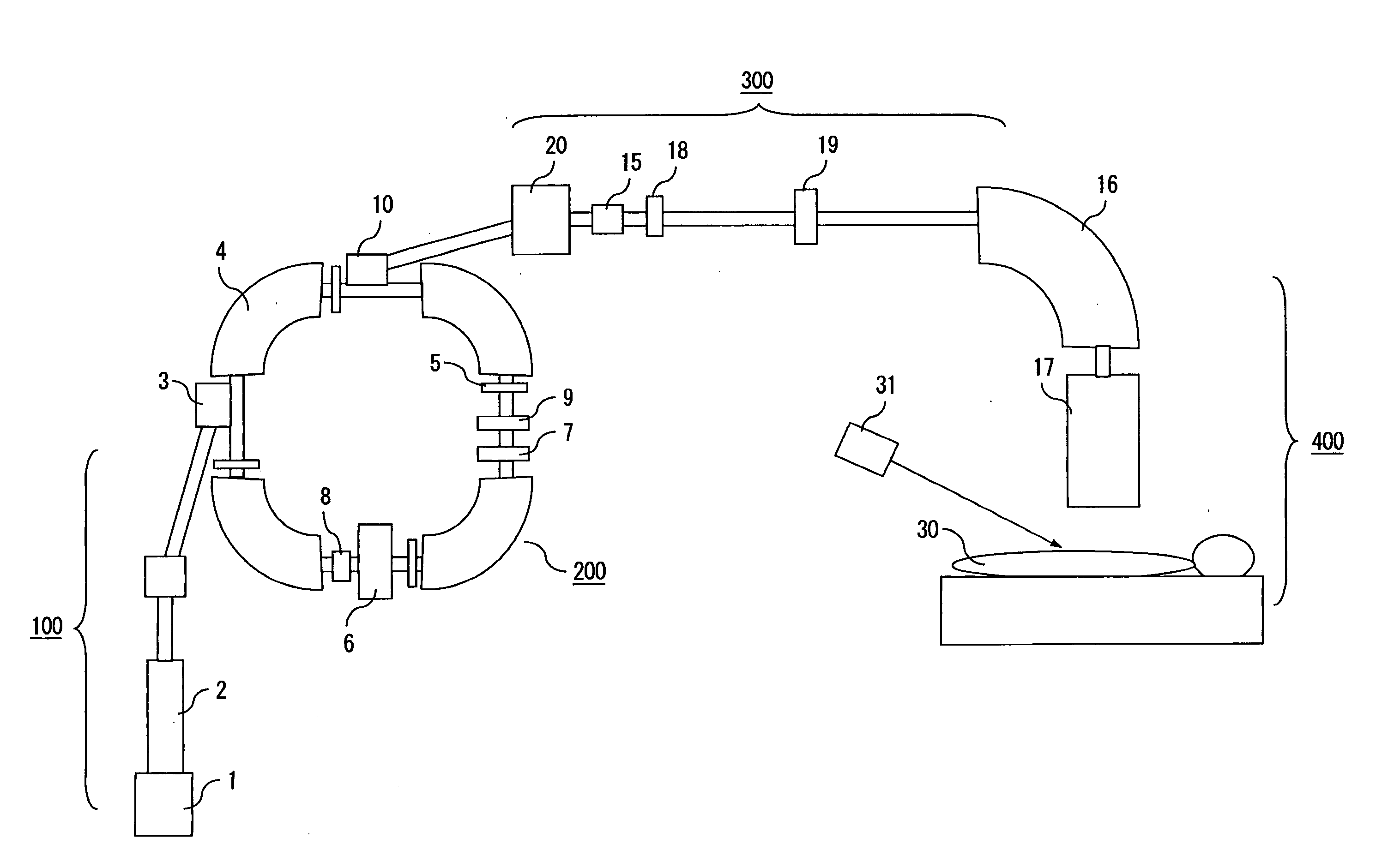
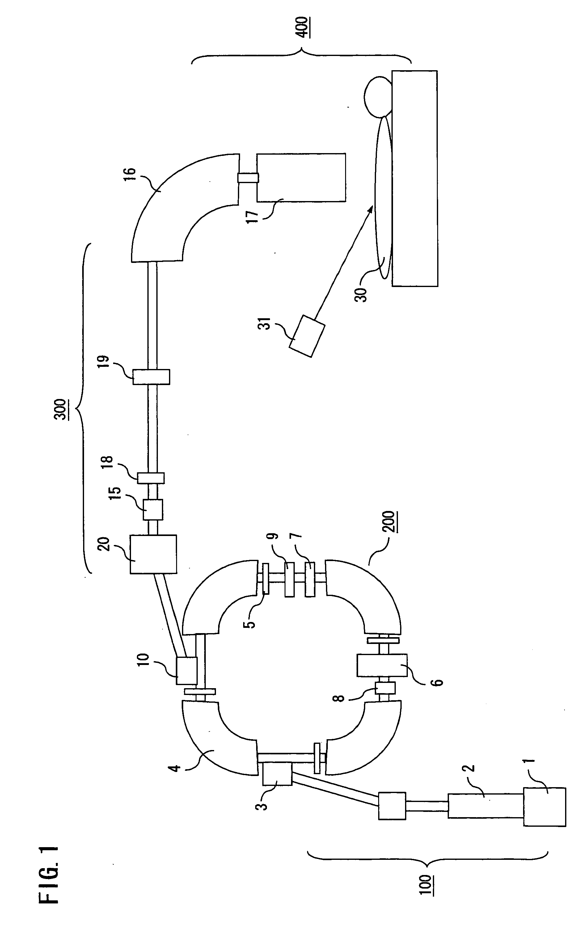
[0038]FIG. 1 is a diagram schematically showing a particle beam radiation system in which a charged-particle beam accelerator 200 and a particle beam radiation therapy system are combined. Referring to this Figure, the charged-particle beam accelerator 200 includes an injection septum 3, four main bending electromagnet units 4, four main quadrupole electromagnet units 5, a high-frequency acceleration unit 6, a sextupole electromagnet unit 7, an RF-KO unit 8 constituting a high-frequency generator, an extraction quadrupole electromagnet unit 9 and an extraction septum 10. The particle beam radiation system includes a beam injection apparatus 100 provided in an upstream stage of the charged-particle beam accelerator 200 for injecting a low-energy beam thereinto. The beam injection apparatus 100 includes an ion source 1 and a linear accelerator 2.

[0039] A charged-particle beam extr...

second embodiment

[0059] A second embodiment of the invention is now described. While the RF-KO unit (radio frequency generating unit) 8 is turned off when the extraction quadrupole electromagnet unit 9 is activated in the foregoing first embodiment as can be seen from FIGS. 6D and 6F, the same advantageous effects as explained above with reference to the first embodiment can be obtained even if the radio frequency generating unit 8 is of a type which generates a frequency-modulated (FM) signal of which frequency is varied over a range of f1 to f2 and is continuously operated as depicted in FIG. 8F. Also, if two such radio frequency generating units 8 are used as in prior art examples to generate FM signals of which phases are offset from each other as shown in FIGS. 9F and 9G, it becomes possible to extract particles more efficiently. The same advantageous effects can also be obtained even if the radio frequency generating unit 8 is of a type which continuously generates a signal containing frequenc...

third embodiment

[0065] A third embodiment of the invention is now described. It is advantageous to install the beam blocking electromagnet unit 18 for generating a magnetic field only during a period between the extraction start signal (FIG. 6B) and the dose complete signal (FIG. 6C) in the beam transport line 300 as shown in FIG. 1 so that no particle beam would be transported to the beam delivery unit 17 even when the beam is extracted at a point in time not between the extraction start signal (FIG. 6B) and the dose complete signal (FIG. 6C) due to noise generated by any of power supplies of the main bending electromagnet units 4, the main quadrupole electromagnet units 5 or the RF-Kp unit 8, for example.

[0066]FIG. 11G shows an operating pattern of the beam blocking electromagnet unit 18. In this embodiment, the bending electromagnet unit 20 disposed in the beam transport line 300 is set to bend the beam by a smaller angle so that the beam deviates from a central axis of a normal beam path and c...


PUM


Abstract

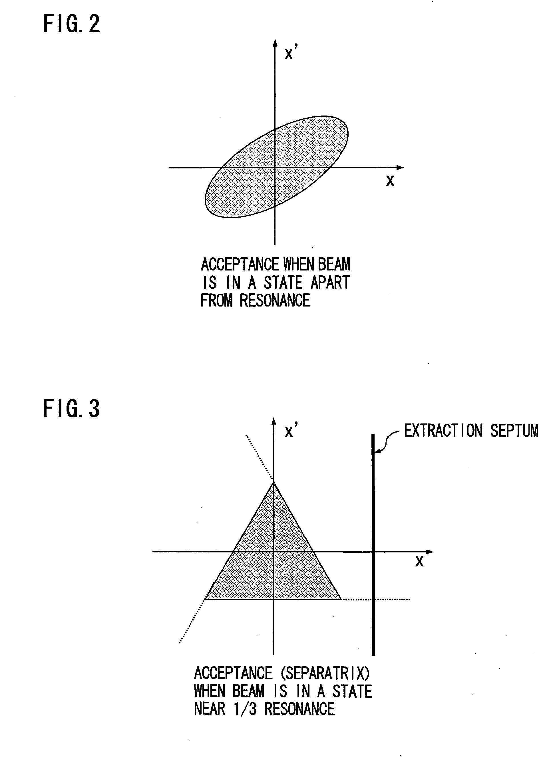
A charged-particle beam accelerator includes an RF-KO unit for increasing the amplitude of betatron oscillation of a charged-particle beam within a stable region of resonance and an extraction quadrupole electromagnet unit for varying the stable region of resonance. The RF-KO unit is operated within a frequency range in which the circulating beam does not go beyond a boundary of the stable region of resonance, and the extraction quadrupole electromagnet unit is operated with appropriate timing as required for beam extraction so that the charged-particle beam is extracted with desired timing.

Description

BACKGROUND OF THE INVENTION [0001] 1. Field of the Invention [0002] The present invention relates to a charged-particle beam accelerator which emits a high-energy particle beam produced by accelerating along a circulating orbit a low-energy beam introduced from an ion source, as well as a particle beam radiation therapy system employing such a charged-particle beam accelerator and a method of operating the particle beam radiation therapy system. [0003] 2. Description of the Background Art [0004] Conventionally, charged-particle beams produced by circular accelerators like a synchrotron are used for physical experiments and medical applications. The circular accelerator generates a particle beam by accelerating charged particles along a circulating orbit. The charged-particle beam is taken out of the circulating orbit and delivered to a location where the beam is used for a physical experiment or medical treatment through a beam transport line. In one beam extraction technique employ...

Claims


Application Information

Patent Timeline
Patent Type & Authority Applications(United States)
IPC IPC(8): A61N5/10G21K5/04H05H7/00H05H7/06H05H7/10H05H13/04
CPCG21K5/04H05H7/10H05H7/06
Inventor NAKANISHI, TETSUYAYOSHIDA, KATSUHISAIKEDA, MASAHIRO
Owner MITSUBISHI ELECTRIC CORP
Learn More