Axial flow fan

a technology of axial flow fan and fan body, which is applied in the direction of domestic cooling apparatus, lighting and heating apparatus, liquid fuel engines, etc., can solve the problems of increasing air flow capacity and noise emission of axial flow fans, and achieve the effects of reducing fluid noise, reducing noise, and reducing fluid nois

Inactive Publication Date: 2005-10-20
JAPAN SERVO CO LTD
View PDF10 Cites 20 Cited by
  • Summary
  • Abstract
  • Description
  • Claims
  • Application Information

AI Technical Summary

Benefits of technology

[0007] An object of the present invention is to provide an axial flow fan which is reduced in fluid noise and allows a further reduction in noise by cutting back the solid-conveyed noise (structure-bone noise) generated by the vibration of the motor or the like that.
[0008] In order to achieve the object stated above, according to the present invention, there is provided an axial flow fan comprising a propeller, an electric motor for driving the propeller, and a venturi portion disposed on the outer circumference side of the propeller and provided on the inner circumferential side of the venturi portion with a bellmouth through which an air flow generated by the revolution of the propeller passes, wherein the bellmouth has an intake portion whose diameter contracts in a curved shape in the direction of the air flow, a cylindrical portion having a cylindrical shape, and a discharge portion whose diameter slantingly expands in the direction of the air flow. With such a bellmouth structure, it is possible to restrain the fluid within the bellmouth from peeling off so as to reduce fluid noise, and to increase the rigidity of the bellmouth so as to raise the point of resonance above the order rotational frequency range in which the fan is used, resulting in an anti-resonance structure. Therefore, not only can fluid noise be reduced but also the solid-conveyed noise due to the vibration of the motor can be reduced, resulting in a further cutback on the overall noise level.
[0009] According to the invention, it is possible to reduce fluid noise and allow a further reduction in noise by cutting back the solid-conveyed (structure-bone) noise generated by the vibration of the motor or the like that.

Problems solved by technology

However, axial flow fans tend to increase in noise emission due to electromagnetic exciting force and propeller revolution along with an increase in air flow capacity.
However, any of these examples of the related art is intended to reduce fluid noise generated by the revolution of the propeller, but is not intended to reduce solid-conveyed noise (structure-bone noise) generated by the vibration of the motor or the like.

Method used


Image

  • Axial flow fan
  • Axial flow fan
  • Axial flow fan

Examples


Embodiment Construction

[0030] An axial flow fan, which is a preferred embodiment according to the present invention, will be described below with reference to the accompanying drawings.

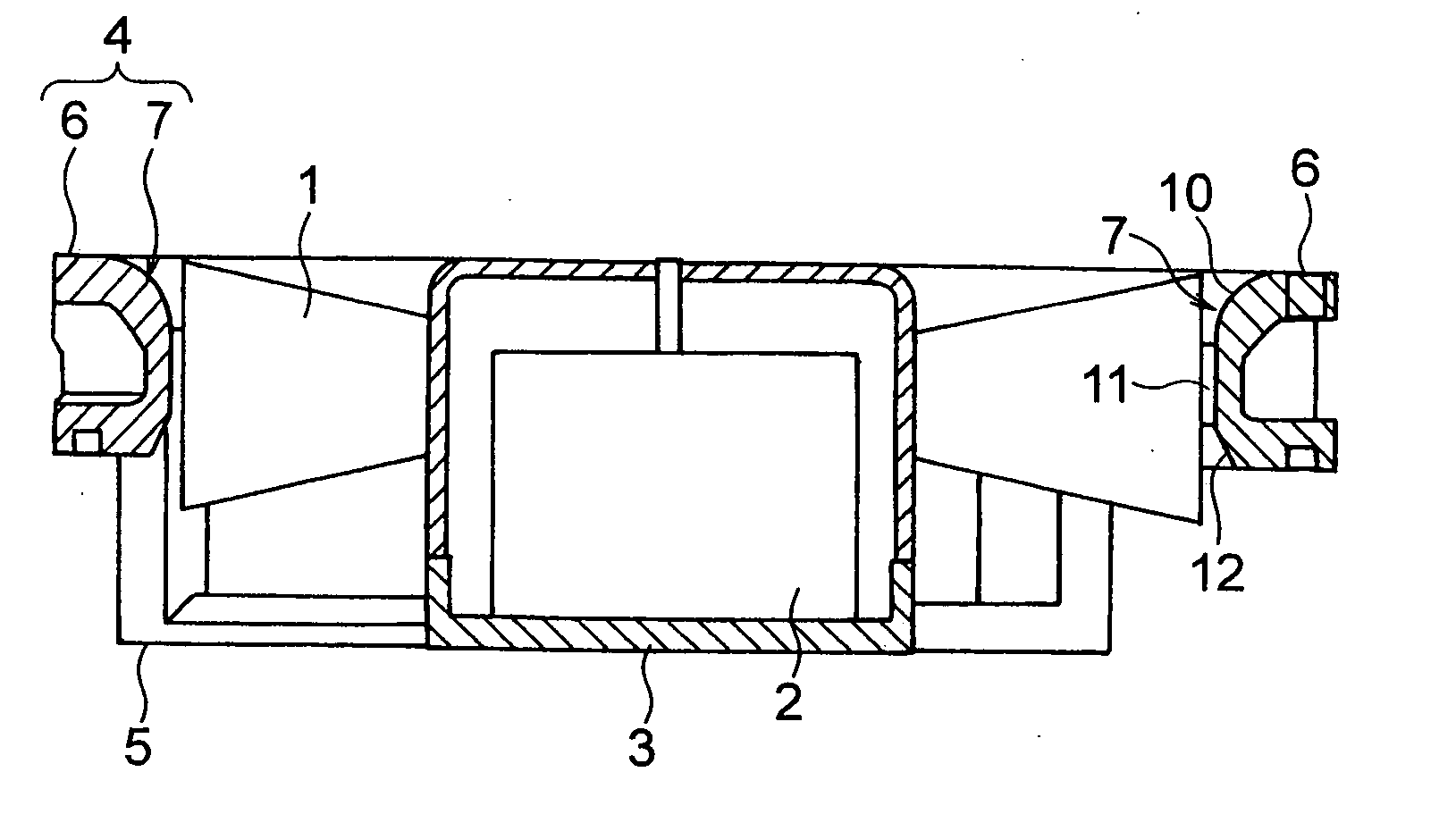
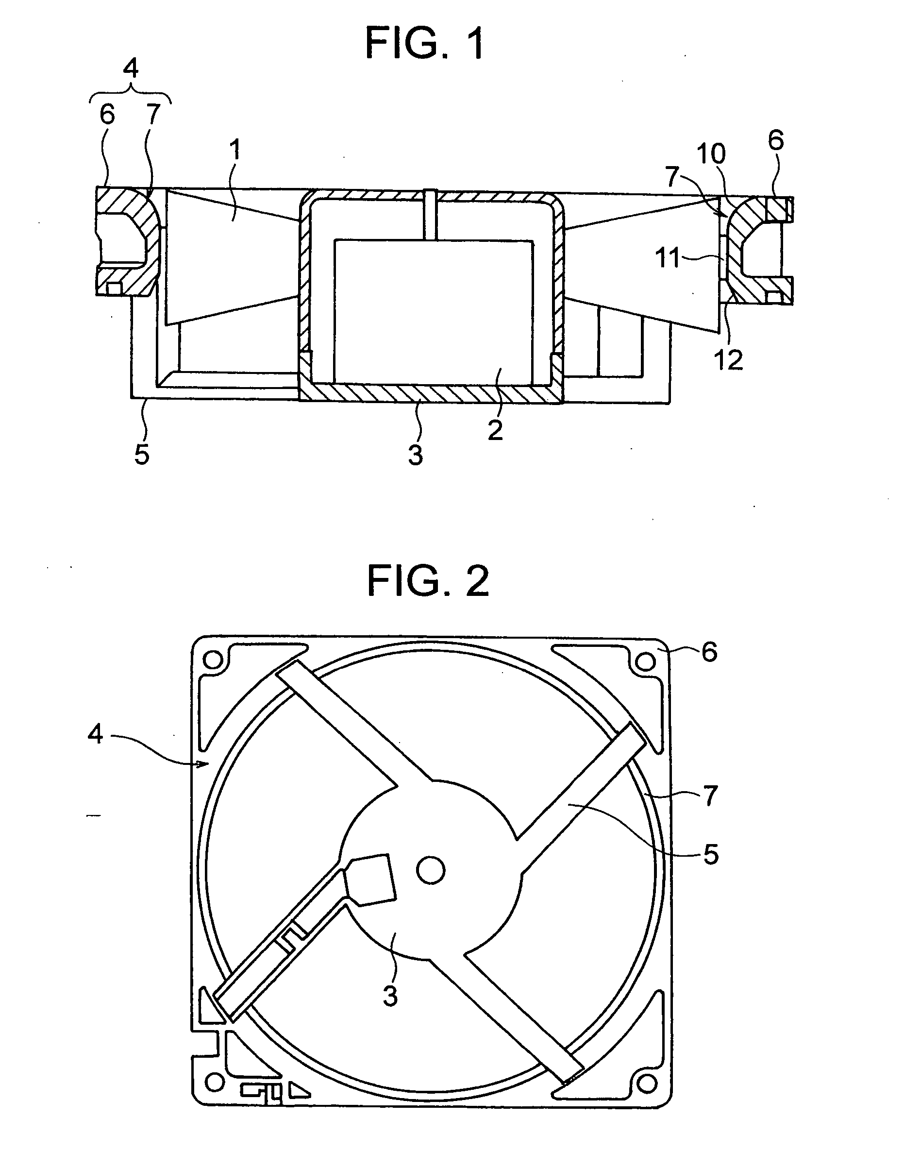
[0031]FIG. 1 is a section view showing an overall structure of the axial flow fan embodying the invention and FIG. 2, a plan view of the same (as viewed from the discharge side (the lower part of FIG. 1)). As shown in these FIG. 1 and FIG. 2, the axial flow fan is provided with a propeller 1 which generates an air flow by rotating, a motor (electric motor) 2 for driving the propeller 1, a plate (motor supporting part) 3 supporting this motor 2, a venturi portion 4 disposed on the outer circumference side of the propeller 1 with a gap between the venturi portion and a tip of the propeller 1, and a plurality of (four in this embodiment) legs (spider) 5 linking the plate 3 and the venturi portion 4. The motor 2 is integrally fitted onto the plate 3, and the propeller 1 is fitted to contain the motor 2 in it. The venturi porti...


PUM


Abstract

In an axial flow fan, for reducing fluid noise and further reducing the noise by suppressing solid-conveyed noise (structure-bone noise) generated by the vibration of an electric motor or the like, the axial flow fan is equipped with a propeller, a motor for driving the propeller, and a venturi portion disposed on the outer circumference side of the propeller and provided on its inner circumferential side with a bellmouth through which an air flow generated by the revolution of the propeller passes, wherein the bellmouth has an intake portion whose diameter contracts in a curved shape in the direction of the air flow, a cylindrical portion having a cylindrical shape, and a discharge portion whose diameter slantingly expands in the direction of the air flow.

Description

BACKGROUND OF THE INVENTION [0001] 1. Field of the Invention [0002] The present invention relates to an axial flow for use in electrical household appliances including refrigerators, various equipment for office automation and information technology (IT) items. [0003] 2. Description of the Related Art [0004] For instance, axial flow fans for cooling purposes are used in many electrical household appliances including refrigerators, various equipment for office automation and IT items. Axial flow fans for use in these products are required to have large air flow capacities for reducing the calorific power and cost of the products in which they are to be installed. However, axial flow fans tend to increase in noise emission due to electromagnetic exciting force and propeller revolution along with an increase in air flow capacity. On the other hand, the demand for noise reduction is also increasingly keen reflecting the pursuit of more pleasant working or living environment. Against thi...

Claims


Application Information

Patent Timeline
Patent Type & Authority Applications(United States)
IPC IPC(8): F01D5/10F04D29/52F04D29/54
CPCF04D29/545
Inventor WATANABE, MASANORIIWASE, TAKUKAWAMATA, SHOUICHISEKIGUCHI, OSAMUTANNO, TARO
Owner JAPAN SERVO CO LTD
Why Eureka
Try Eureka