
Battery employing thermally conductive polymer case

a polymer case and battery technology, applied in the field of alkaline batteries, can solve the problems of poor tolerance to deep discharge, impractical power source for electric vehicles, hybrid electric vehicles,

Inactive Publication Date: 2005-10-20
CHEVRON TECH VENTURES
View PDF3 Cites 73 Cited by
  • Summary
  • Abstract
  • Description
  • Claims
  • Application Information

AI Technical Summary

Benefits of technology

[0010] The present invention includes a battery having at least one group of electric power-generating elements each comprising at least a positive electrode, a negative electrode and a separator; and a battery case containing the group of electric power-generating elements. The battery case is formed from a mixture which includes a matrix material selected from the group consisting of plastics, polymers, resins or combina

Problems solved by technology

However, their low energy density (about 30 Wh / kg) and their inability to reject heat adequately, makes them an impractical power source for an electric vehicles (EV), hybrid electric vehicles (HEV) and 2-3 wheel scooters / motorcycles.
In addition, electric vehicles using lead-acid batteries have sluggish acceleration, poor tolerance to deep discharge, and a battery lifetime of only about 20,000 miles.
For example, in electric vehicles and in hybrid vehicles, the weight of the batteries is a significant factor.
First, ambient heat due to the operation of the vehicle in hot climates.
Third, a tremendous amount of heat is generated during overcharge due to gas recombination.
Therefore, it was not very difficult to provide the batteries and modules (bundles) of such batteries with effective thermal cooling even when only a portion of the case was exposed to the cooling medium.
Unfortunately, these plastics generally have relatively low thermal conductivity, and as such their use generally places severe limitations on the ability of the batteries to be cooled efficiently, and therefore more elaborate systems are needed to provide both the structural integrity and thermal management of the batteries.

Method used


Image

  • Battery employing thermally conductive polymer case
  • Battery employing thermally conductive polymer case
  • Battery employing thermally conductive polymer case

Examples


Embodiment Construction

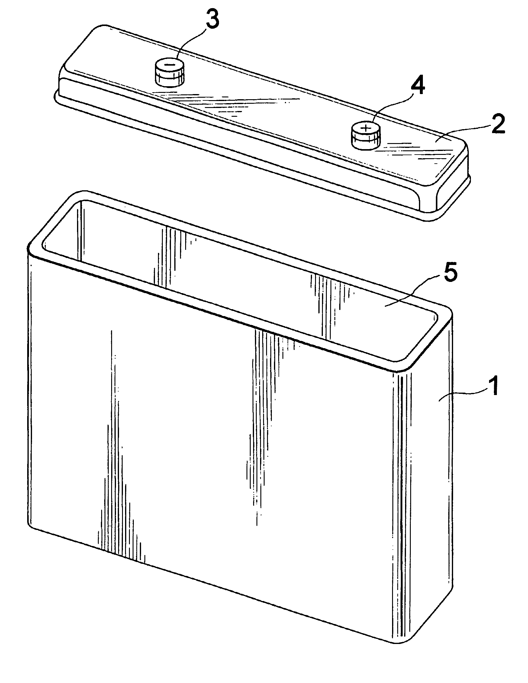
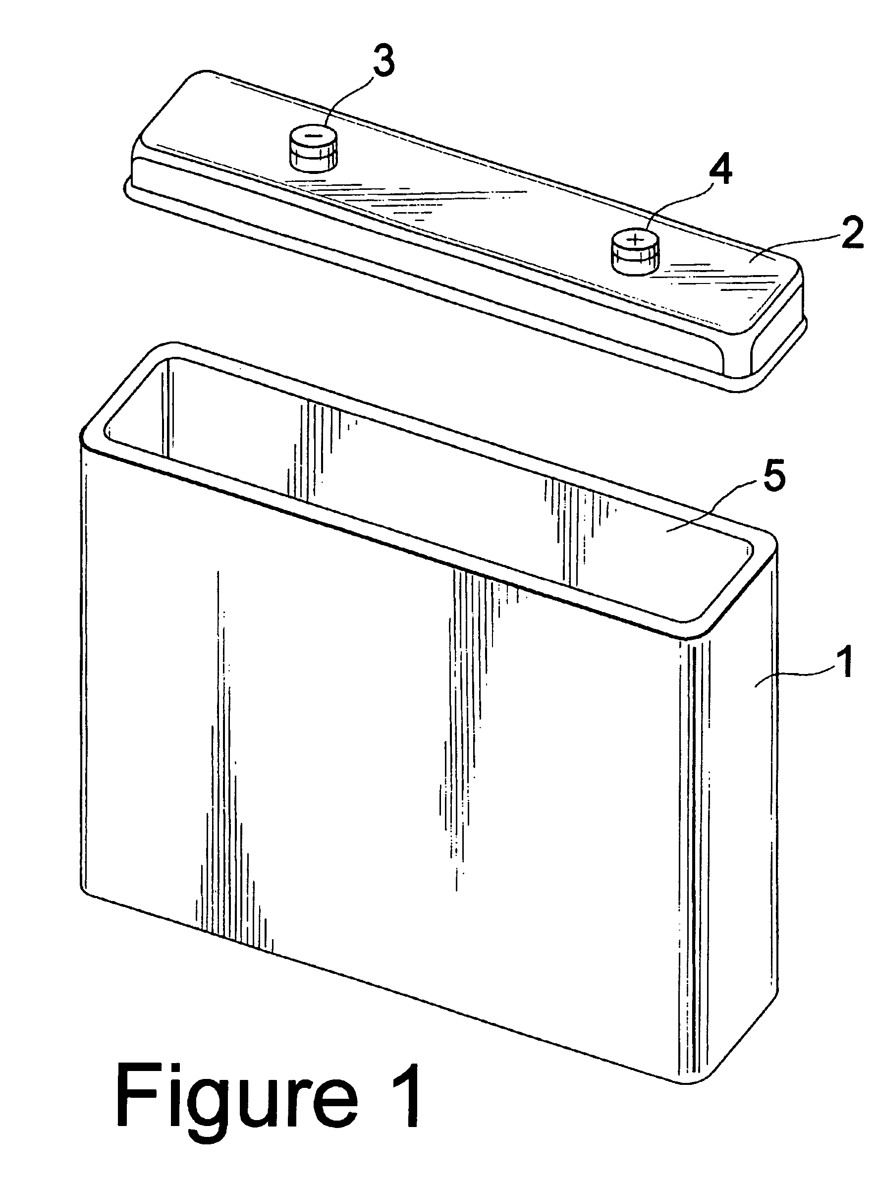
[0018] The present invention includes battery cases formed from a polymeric material which has enhanced thermal conductivity and batteries which include such cases. Schematic illustrations of examples of secondary batteries and their cases embodying the present invention are shown in FIGS. 1 to 5, however, the present invention is not limited to these embodiments. FIG. 1 illustrates a battery case of the present invention comprising a container 1 and a lid 2 which are formed from the enhanced thermal conductivity polymeric material. The lid 2 is provided with a negative electrode terminal 3 and a positive electrode terminal 4. The container 1 and the lid 2 are welded by fusion or melt bonding with heat or other means such as vibration or sonic welding.

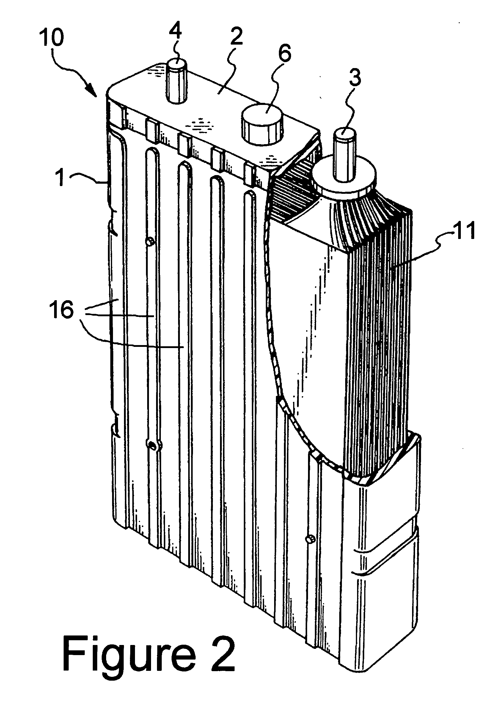
[0019]FIG. 2 depicts an embodiment of a battery 10 of the present invention which includes a rectangular battery container 1 formed from the enhanced thermal conductivity polymeric material. The battery contains an electrode group 11 ...


PUM


Abstract

A battery having at least one group of electric power-generating elements each comprising at least a positive electrode, a negative electrode and a separator; and a battery case containing the group of electric power-generating elements. The battery case is formed from a mixture which includes a matrix material selected from the group consisting of plastics, polymers, resins or combinations thereof. The mixture further includes a thermally conductive, electrically insulating material distributed throughout the matrix material. The thermally conductive material has a thermal conductivity at least one order of magnitude higher than the thermal conductivity of the matrix material. The present invention also includes battery cases (lids and containers) used in making the batteries and formed of the mixture.

Description

FIELD OF THE INVENTION [0001] The present invention relates generally to electrochemical cells or batteries and more specifically to alkaline batteries. In particular the present invention pertains to alkaline batteries having plastic cases formed from blended polymer materials with enhanced thermal conductivity. BACKGROUND OF THE INVENTION [0002] Rechargeable batteries are used in a variety of industrial and commercial applications such as fork lifts, golf carts, uninterruptable power supplies, and electric vehicles. Rechargeable lead-acid batteries are a useful power source for starter motors for internal combustion engines. However, their low energy density (about 30 Wh / kg) and their inability to reject heat adequately, makes them an impractical power source for an electric vehicles (EV), hybrid electric vehicles (HEV) and 2-3 wheel scooters / motorcycles. Electric vehicles using lead-acid batteries have a short range before requiring recharge, require about 6 to 12 hours to rechar...

Claims


Application Information

Patent Timeline
IPC IPC(8): B65D19/10H01M10/50H01M50/103H01M50/117H01M50/121H01M50/122H01M50/131H01M50/157H01M50/16H01M50/162
CPCH01M2/024H01M2/0262H01M2/0277H01M2/0282H01M2/0287H01M2/029H01M10/5059H01M2/0482H01M10/345H01M10/5004H01M10/5032H01M10/504H01M2/0295H01M10/653H01M10/647H01M10/6557H01M10/613Y02E60/10H01M50/124H01M50/162H01M50/103H01M50/121H01M50/157H01M50/117H01M50/16H01M50/122H01M50/131
Inventor PUTTAIAH, RAJEEVSMAGA, JOHNHIMMLER, RONALDHIGLEY, LIN R.MULLER, MARSHALL D.
Owner CHEVRON TECH VENTURES
Learn More