
Systems, methods and apparatus for image annotation

an image annotation and system technology, applied in the field of annotation images, can solve the problems of increasing the annual cost of modifying the viewers, logistical challenges, and the inability of medical imaging devices to include new annotation calculations and operations, and the inability to accurately predict the effect of the annotation

Inactive Publication Date: 2005-10-20
GENERAL ELECTRIC CO
View PDF27 Cites 41 Cited by
  • Summary
  • Abstract
  • Description
  • Claims
  • Application Information

AI Technical Summary

Benefits of technology

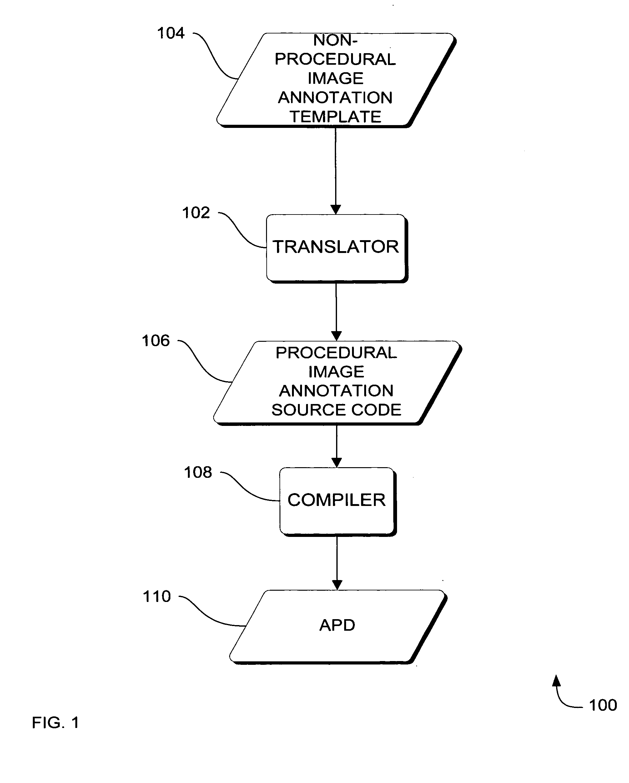
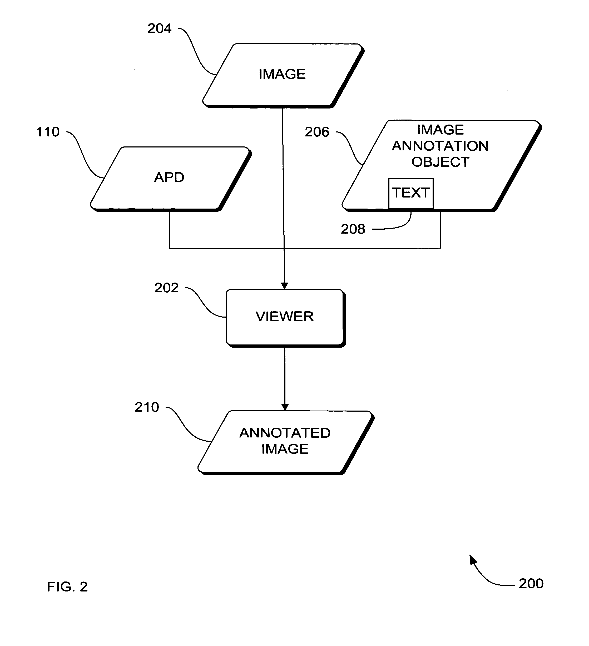
[0015] In another aspect, an image viewer invokes execution of the annotation instructions in the APD on an imaging system, thus prompting annotation of an image using data from an image annotation object, to create an annotated image. The annotation instructions are native to the imaging system, thus interpreting the annotation instructions on the imaging system is not required; therefore, a run-time interpreter is not required to execute the annotation instructions. The need to rewrite the image viewer to include annotation instructions is reduced by packaging the annotation instructions in the APD for ready execution by the imaging system without changes to the imaging viewer. The convenient packaging of the annotation instruction more readily and conveniently allows for consistent deployment of annotation calculations and operations among medical imaging systems.

Problems solved by technology

Calculation of annotation in medical images in conventional systems frequently involves complex arithmetic calculations and special string operations.
The decision as to how often to modify the source code of the viewers of the medical imaging devices is a selection between either reducing the frequency of viewer modifications which reduces the annual costs of upgrading but which also the effect of also reducing the frequency that the calculations and operations are improved; or increasing the frequency of viewer modifications which increases the frequency that the calculations and operations are improved, but also increases the annual costs of modifying the viewers.
However, upgrading each medical imaging device to include new annotation calculations and operations is a logistical challenge.
The logistical challenges slow down the process of upgrading and results in circumstances where not all of the medical imaging devices are upgraded at the same time.
As a result, there is inconsistent image annotation among the medical imaging devices in the field.
A lack of consistent annotation from one device to another in the field is distracting and less efficient to the work of the people who use the machines, such as the operator technicians, and those who review the images, such as radiologists.
Unfortunately, the run-time interpreters increase the time to load an image by a significant margin because run-time interpreters are inherently slower than systems that execute native code.
In addition, conventional mechanisms for managing annotation on imaging devices are also inconvenient to implement on imaging devices that are based on C++ objects using Java code because special interfaces that convert the Java code into C++ code are needed.
The Java-to-C++ interfaces are less desirable because the mechanized interfaces often yield C++ code that is not optimized.
The less than optimal code executes slower, and requires more memory to execute.
Furthermore, the conversion from Java to C++ is an extra step in the process that increases the total time of processing on the imaging device.
Unfortunately, conventional annotation tools do not readily lend themselves to JAVA-based image viewers.

Method used


Image

  • Systems, methods and apparatus for image annotation
  • Systems, methods and apparatus for image annotation
  • Systems, methods and apparatus for image annotation

Examples


an embodiment

Methods of an Embodiment

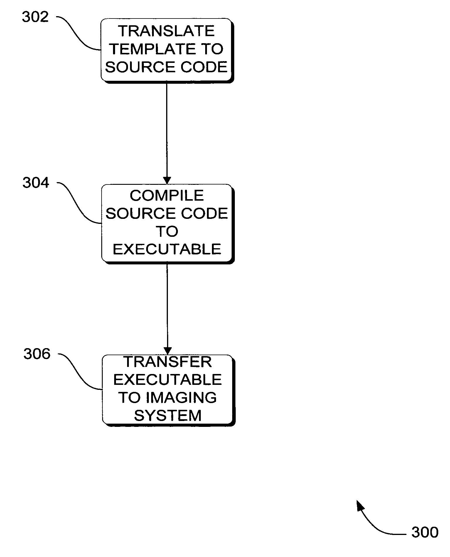
[0045] In the previous section, system level overviews of the operation of embodiments were described. In this section, particular methods performed by the computers of such an embodiment are described by reference to a series of flowcharts. Describing the methods by reference to a flowchart enables one skilled in the art to develop such programs, firmware, or hardware, including such instructions to carry out the methods on a processor of the of suitable computers executing the instructions from computer-readable media. Methods 300-400 are performed by a program executing on, or performed by firmware or hardware that is a part of, a computer, such as computer 1202 in FIG. 12.

[0046]FIG. 3 is a flowchart of a method 300 performed by a computer according to an embodiment. Method 300 generates an image annotation executable, such as an annotation presentation description (APD) 110, from a non-procedural image annotation template 104 to annotate an image 204.

[0...


PUM


Abstract

Systems, methods and apparatus are provided through which a non-procedural image annotation template is translated into source code, and compiled into an image annotation executable that has native computer instructions for an imaging system. In some embodiments, an image viewer on the imaging system accesses the native instructions and invokes the native instructions to annotate an image with text information. In some embodiments, the imaging system is a magnetic resonance, computer tomography, X-ray, ultrasound, or positron emission tomography imaging system.

Description

FIELD OF THE INVENTION [0001] This invention relates generally to annotating images, and more particularly to annotating medical diagnostic images. BACKGROUND OF THE INVENTION [0002] Images are often annotated with textual information. The textual information often provides descriptive or identifying information of the image. For example, an image is annotated with information that describes the owner or author of the image, or a title or label of the image, or a sequence number of the image. Annotation is a modification of the image to the extent that the textual information is visually perceptible in the image to a human. One example is a modification of a bit map to the extent that the bitmap visually represents the textual characters. [0003] In medical imaging, images are generated from scans of patients. Similar to images in general, the medical images of patients are often annotated with textual information. The textual annotation includes demographics of the image, such as an...

Claims


Application Information

Patent Timeline
IPC IPC(8): G06F9/44G06F9/45
CPCG06F8/51
Inventor SKINNER, JOHN V.
Owner GENERAL ELECTRIC CO
Learn More