Amphibious robot devices

a robot device and amphibious technology, applied in underwater equipment, special-purpose vessels, instruments, etc., can solve the problems of personnel being exposed to situations with the enemy, personnel being in harm's way, and only gaining information at considerable risk

Inactive Publication Date: 2005-10-27
IROBOT CORP
View PDF8 Cites 49 Cited by
  • Summary
  • Abstract
  • Description
  • Claims
  • Application Information

AI Technical Summary

Benefits of technology

[0009] According to embodiments of the present invention, devices for navigating in a fluid medium having a solid boundary include a vehicle body and a fin attached to the vehicle body. The fin is configured to oscillate relative to the body such that interaction between the fin and the fluid medium produces propulsive forces that propel the vehicle body in a desired direction in the fluid medium. The fin is also configured to rotate relative to the body along a transverse axis such that engagement between the fin and the solid boundary propels the vehicle body in a desired direction on the solid boundary. In this configuration, the device can move in both a fluid medium, such as water, and on land. The device can be equipped with sensors to gather information, and can be used, for example, in a military intelligence operation to gather information without endangering personnel.
[0010] According to further embodiments of the present invention, methods of navigating a device in a fluid medium having a solid boundary include releasing the device to the fluid medium. The device includes a vehicle body, a fin attached to the vehicle body, and a controller for controlling and / or driving the fin. The fin can be moved with the controller such that interaction between the fin and the fluid medium produces propulsive forces that propel the vehicle body in a desired direction in the fluid medium. The device can be propelled to a solid boundary of the fluid medium. The fin can be moved with the controller such that engagement between the fin and the solid boundary propels the vehicle body in a desired direction on the solid boundary to a predetermined location.
[0011] In some embodiments, a device for navigating in a fluid medium having a solid boundary includes a vehicle body and a fin attached to the vehicle body. The fin includes a flexible portion having an elongated shaft therein, and a rigid tine coupled to the shaft, wherein the flexible portion is movable from a first position adjacent the tine and a second position extended away from the tine such that the tine is exposed. The fins can be used to move sediment, for example, to expose a mine or other object, and / or to bury the device to reduce the chance of detection. For example, the fin can be configured to propel the device through water when the flexible portion is in the first position. The tines may be configured to engage and move portions of the solid boundary when the flexible portion is in the second position extending away from the flexible portion.

Problems solved by technology

Accurate and timely information can be crucial to success in military operations, but in some circumstances, information can be gained only at considerable risk to personnel.
Not all desirable information is, however, accessible via remote sensing, and personnel continue to be in harm's way.
One example is personnel swimming ashore and moving inland through hostile territory to gather timely information on enemy strengths and positions, which can expose the personnel to situations with the enemy, such as capture and attack.
Another example is the placing of neutralization charges on submerged mines, which often can be at least partly covered with sediment and, therefore, difficult to neutralize.
As a result, a large unwieldy neutralizing charge is typically carried and placed by hand over a buried mine.
Despite such close placement, a sediment-covered mine may not be effectively neutralized because of the shielding effect of the overlying sediment.
These techniques expose divers and / or dolphins used for this task to considerable risk.
Navigation can pose a challenge in an underwater environment, especially when land use is also desired, such as in intelligence gathering.
Swimming, ambulating and / or digging impose different design constraints on a device.
Some proposed terrestrial robots use legs with numerous degrees of freedom that require considerable sensing and computation to control their use, making movement slow and costly.
Proposed leg and wheel-resembling appendages are inefficient for swimming.
Such designs may not be well-suited for movement in water or other fluid environments.

Method used


Image

  • Amphibious robot devices
  • Amphibious robot devices
  • Amphibious robot devices

Examples


Embodiment Construction

[0027] The present invention will now be described more fully hereinafter with reference to the accompanying figures, in which embodiments of the invention are shown. This invention may, however, be embodied in many different forms and should not be construed as limited to the embodiments set forth herein. Like numbers refer to like elements throughout. In the figures, layers, components, or features may be exaggerated for clarity.

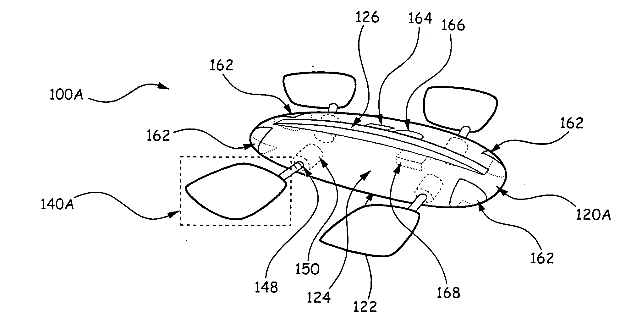
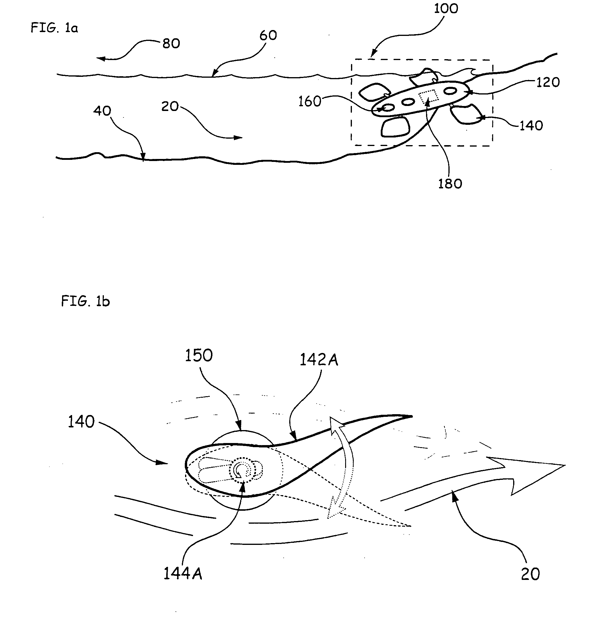
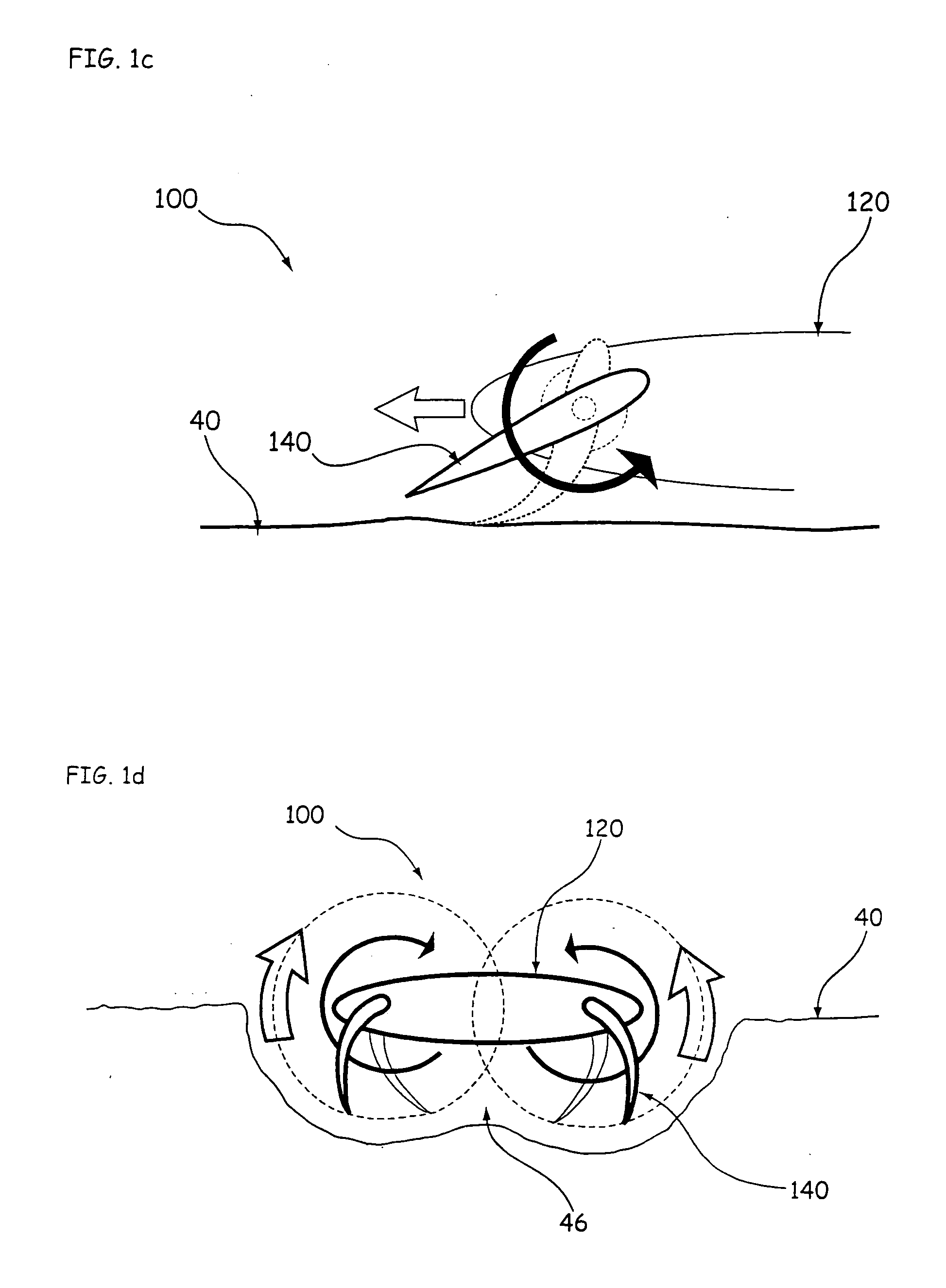
[0028]FIG. 1a illustrates a device 100 according to embodiments of the present invention that includes a body 120, fins 140, and transducer(s) 160. As shown, the device 100 includes a payload 180 that can be carried within or attached to the body 120, for example, to neutralize another object. The device 100 can swim in the water 20, such as at an intermediate depth, near the substratum 40, and / or at the surface 60. The substratum 40 can be a solid boundary of either air 80 or water 20, such as the sea bottom, sediment, ground, beach, river bank, swamp, o...


PUM


Abstract

Devices for navigating in a fluid medium having a solid boundary include a vehicle body and a fin attached to the vehicle body. The fin is configured to oscillate relative to the body such that interaction between the fin and the fluid medium produces propulsive forces that propel the vehicle body in a desired direction in the fluid medium. The fin is also configured to rotate relative to the body along a transverse axis such that engagement between the fin and the solid boundary propels the vehicle body in a desired direction on the solid boundary.

Description

RELATED APPLICATIONS [0001] This application is a continuation application of U.S. patent application Ser. No. 10 / 848,330, filed May 18, 2004, which claims the benefit of priority from U.S. Provisional Application Ser. No. 60 / 471,626, filed May 19, 2003, the disclosures of which are hereby incorporated by reference in their entireties.STATEMENT OF GOVERNMENT SUPPORT [0002] This invention was made with Government support under Small Business Innovation Research (SBIR) Program Contract Nos. N00014-00-C-0445, N00014-02-M-0209, and N00014-05-C-0277 awarded by The United States Navy. The Government has certain rights in the invention.FIELD OF THE INVENTION [0003] This invention relates generally to methods and devices for robot devices, and more specifically, to amphibious robot devices. BACKGROUND OF THE INVENTION [0004] Accurate and timely information can be crucial to success in military operations, but in some circumstances, information can be gained only at considerable risk to pers...

Claims


Application Information

Patent Timeline
Patent Type & Authority Applications(United States)
IPC IPC(8): B60F3/00B63G8/00B63H1/30B63H1/36E02F5/00F41H11/16F41H13/00F42B12/36F42B19/00G05D3/00
CPCB60F3/0007B63H1/36E02F5/006F42B19/00F41H13/00F42B12/365F41H11/16
Inventor HOBSON, BRETT W.KEMP, MATHIEUMOODY, RYANPELL, CHARLES A.VOSBURGH, FREDERICK
Owner IROBOT CORP
Why Eureka
Try Eureka