
Liquid-cooled projector

Active Publication Date: 2005-10-27
SHARP NEC DISPLAY SOLUTIONS LTD
View PDF9 Cites 13 Cited by
  • Summary
  • Abstract
  • Description
  • Claims
  • Application Information

AI Technical Summary

Benefits of technology

[0006] It is an object of the present invention to provide a liquid-cooled projector that incorporates a means for cooling a component that is to be cooled by a cooling liquid, and moreover, for constantly maintaining the component that is to be cooled at or below a prescribed temperature.
[0012] The present invention features a configuration in which the liquid-cooling unit allows cooling of a component that is to be cooled inside a projector by a cooling liquid, and moreover, that allows stable and continuous circulation of the cooling liquid. The present invention thus has the effect of allowing the component that is to be cooled inside the projector to be maintained at or below a prescribed temperature and of enabling a solution to the problems of large size and increased noise of the fan in an air-cooled system.

Problems solved by technology

However, the demand for higher luminance in recent years has resulted in the use of lamps with higher power, and this has resulted in the generation of even more heat in the optical modulation element and cold mirror.
This change has necessitated larger air-cooling fans for air-cooled designs, with the attendant disadvantage of increased noise.
As described above, the necessity for a larger air-cooling fan when air-cooling is used in a high-luminance projector and the problem of the attendant increase in noise is a common problem.

Method used


Image

  • Liquid-cooled projector
  • Liquid-cooled projector
  • Liquid-cooled projector

Examples


working example 1

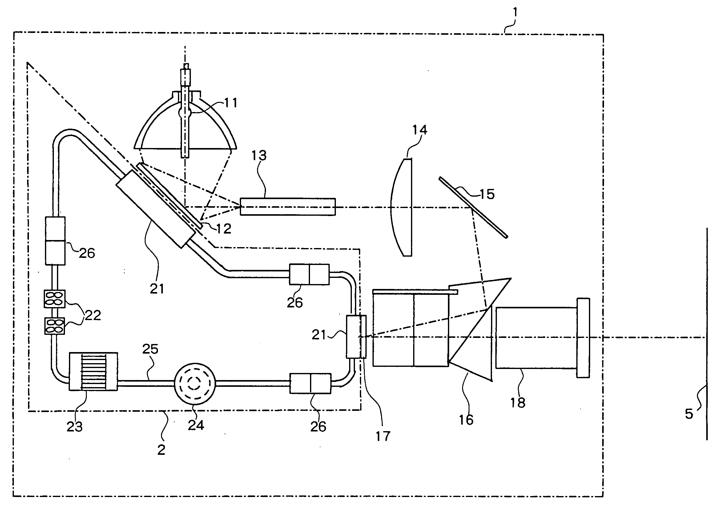
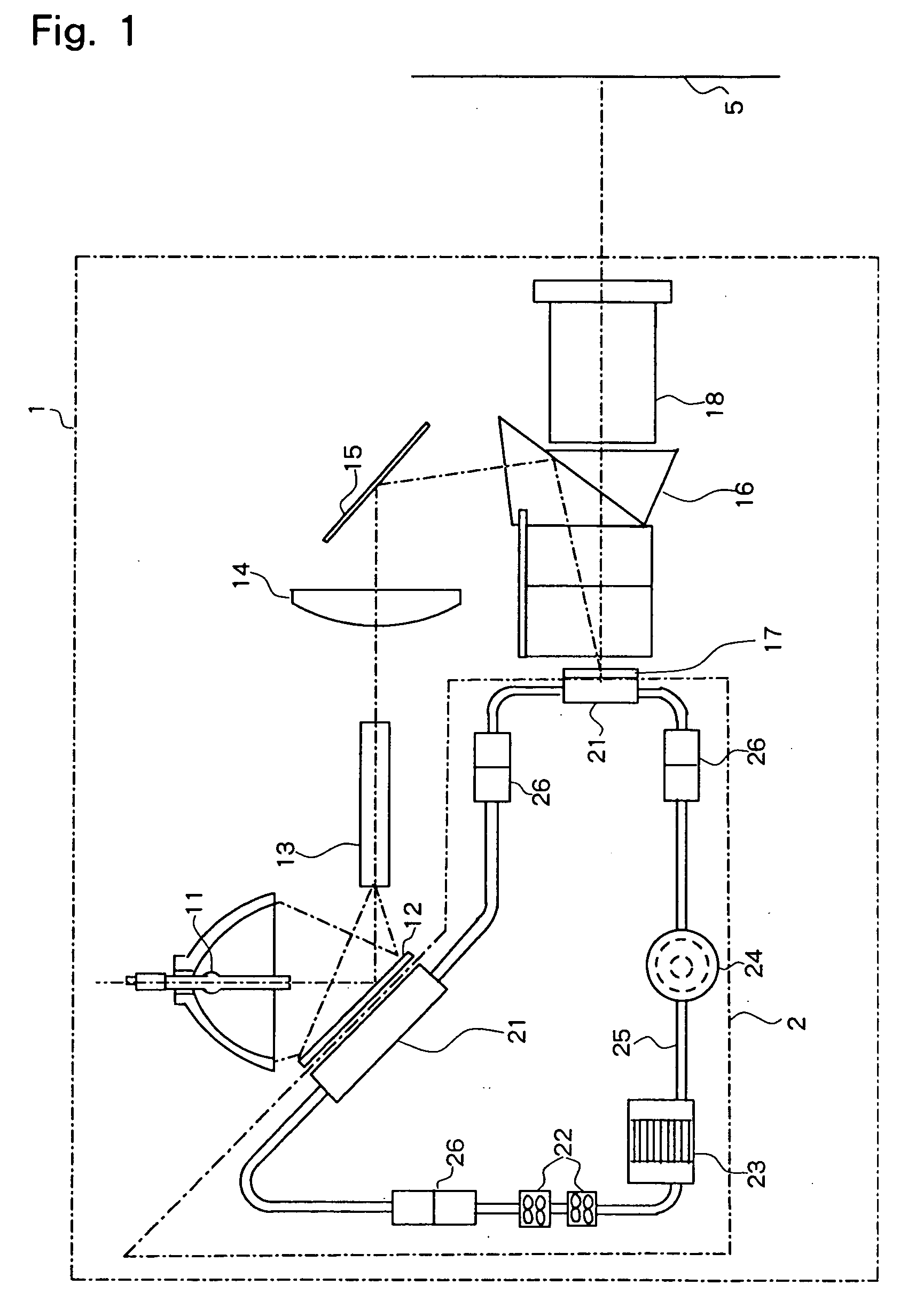
[0020] Explanation next regards the first working example of the liquid-cooled projector that is provided with the liquid-cooling unit of the present invention with reference to the accompanying figures. As shown in FIG. 1, projector 1 of the present working example is provided with: light source 11, which is a lamp provided with a reflecting mirror; cold mirror 12 for eliminating from the illumination system the infrared rays in the light beam that is emitted from light source 11; rod integrator 13 for producing a plurality of light source images; relay lens 14 and reflecting mirror 15 for directing light to optical modulation element 17; prism 16 for realizing color separation and combination; optical modulation element 17, projection lens 18 for projecting light on screen 5; and liquid-cooling unit 2 for cooling optical modulation element 17 and cold mirror 12.

[0021] Liquid-cooling unit 2 is provided with: liquid-cooling jacket 21 that is arranged on the rear of optical modulati...

working example 2

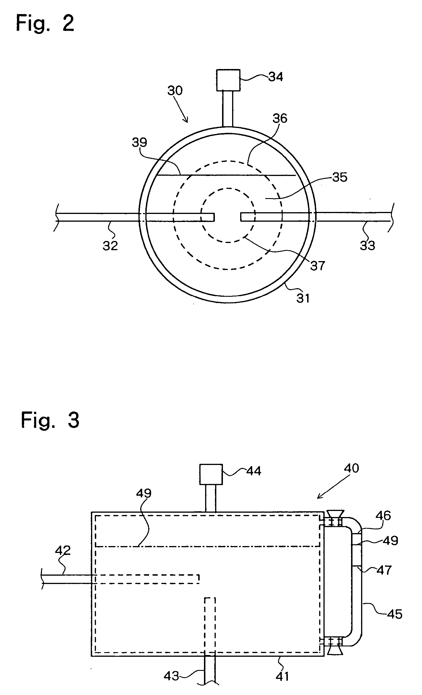
[0025] Reserve tank 24 can be conceived in a variety of forms, and working example 2 shows one working example of the reserve tank. As shown in FIG. 2, in reserve tank 30 of this working example, tank 31 is spherical, and this spherical tank 31 is provided with inflow nozzle 32, outflow nozzle 33, and injection port 34. Maximum liquid level mark 36 and minimum liquid level mark 37 are provided on liquid amount display part 35 that can be observed and that is provided on tank 31 itself. Inflow nozzle 32 and outflow nozzle 33 have open ends that are more centrally located than minimum liquid level mark 37. Thus, even when bubbles are generated and circulate inside this liquid-cooling unit 2, the bubbles combine with the air layer that is above liquid level 39 inside reserve tank 30. Outflow nozzle 33 is similarly positioned more centrally than minimum liquid level mark 37, whereby only the cooling liquid that has no bubbles is caused to flow from reserve tank 30, whereby idle running ...

working example 3

[0027] Working example 3 shows another working example of the reserve tank. Reserve tank 40 of the present working example shown in FIG. 3 is a working example for a case in which liquid level display part 45, can be observed but cannot be directly shown on tank 41, which is the cooling liquid storage unit of reserve tank 40. Liquid level display part 45 is a pipe that allows observation of its interior; maximum liquid level mark 46 and minimum liquid level mark 47 are shown on this pipe. When the liquid level is checked, the orientation of reserve tank 40 is arranged with injection port 44 at the upper side such that injection port 44 is in contact with the air layer.


PUM


Abstract

A liquid-cooled projector incorporates a means for cooling a component that to be cooled by means of a cooling liquid, and moreover, can constantly maintain the temperature of the component to be cooled at a prescribed temperature or below. A liquid-cooling jacket for cooling either one or both of the optical modulation element and cold mirror, which are the components that are to be cooled, one or a plurality of radiators, one or a plurality of reserve tanks, and one or a plurality of circulation pumps are connected together by piping. The components that are to be cooled are maintained at or below the prescribed temperature by circulating the cooling liquid through the system, which can further be separated at any position by couplers. By collecting the air that is generated in the cooling system in the reserve tank, idle running of the circulation pump can be prevented, and the effect of expansion and shrinkage in the volume of the cooling liquid can be mitigated.

Description

BACKGROUND OF THE INVENTION [0001] 1. Field of the Invention [0002] The present invention relates to a projector that incorporates a mechanism for a component that is to be cooled by a coolant. [0003] 2. Description of the Related Art [0004] Cooling the heat-generating parts within a projector is crucial for extending the life of constituent components and improving the reliability of the projector. In particular, the optical modulation element and cold mirror must be cooled to below a prescribed temperature. For this purpose, a method has been disclosed in Japanese Patent Laid-Open Publication No. 2004-77883 in which a heat sink having heat-radiation fins is directly attached to the optical modulation element and this heat sink is then air-cooled by means of an air-cooling fan. Japanese Patent Laid-Open Publication No. 2000-77585 discloses a configuration in which a Peltier element is interposed between optical elements and thin heat sink is then air-cooled by means of an air-cooli...

Claims


Application Information

Patent Timeline
IPC IPC(8): F25D3/00F28D15/00G03B21/16G03B21/20H04N5/74
CPCF28D15/00H04N9/3141G03B21/20G03B21/16
Inventor TAKEUCHI, KATSUYUKI
Owner SHARP NEC DISPLAY SOLUTIONS LTD
Learn More