
Impedance controlled output driver

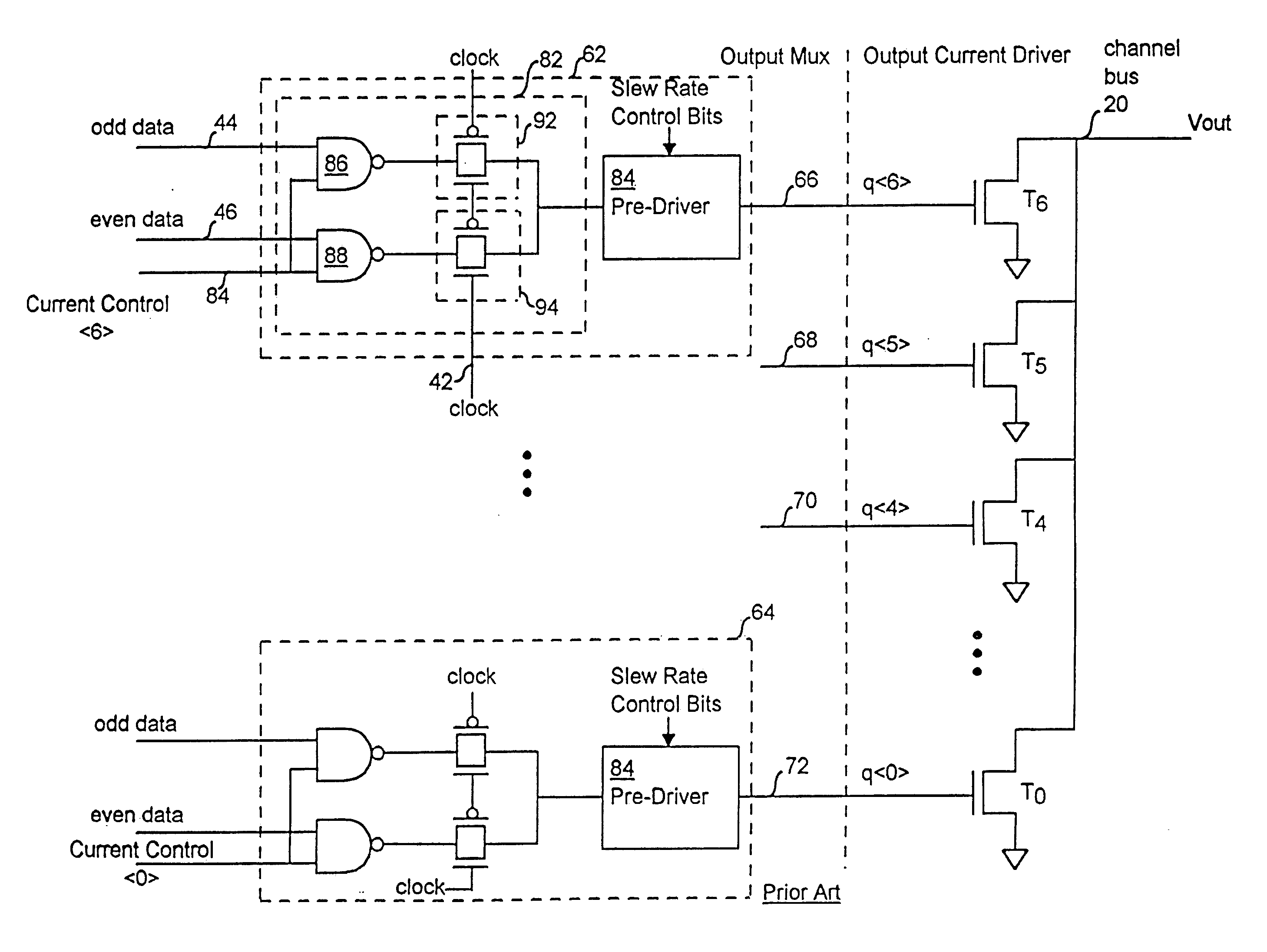
a technology of impedance control and output driver, which is applied in the direction of pulse manipulation, pulse technique, instruments, etc., can solve the problems of difficulty in matching the delays and slew rates of each q-node under all process, voltage and temperature conditions, and achieve the effect of simplifying the implementation of adjustable operating current, simplifying the design of impedance controlled driver, and controlling switching characteristics

Inactive Publication Date: 2005-10-27
RAMBUS INC
View PDF17 Cites 10 Cited by
  • Summary
  • Abstract
  • Description
  • Claims
  • Application Information

AI Technical Summary

Benefits of technology

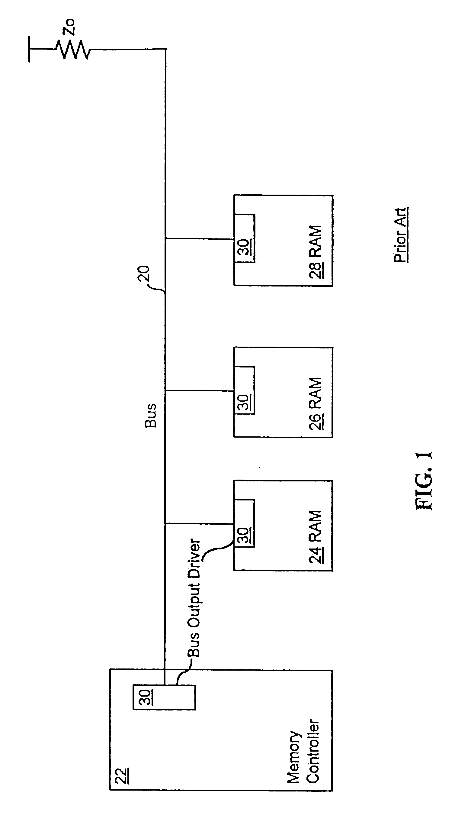
The present invention is about an output driver that can adjust its operating current and slew rate. It uses a single control node to achieve this, which simplifies the design and ensures controlled switching characteristics. The driver includes an output current driver that can adjust its output current and a duty cycle compensator to maintain the duty cycle of the control signal. Additionally, a kickdown circuit is used to aid the predriver in driving the control signal to ground. The driver also uses a regulated power supply and a charge compensator to maintain the voltage level. Overall, the output driver has controlled and determinable output impedance, minimizes reflections from other drivers on the bus, and ensures a stable output current on the bus.

Problems solved by technology

However, when using multiple q-nodes to drive a single channel, it is difficult to match the delays and slew rates of each q-node under all process, voltage and temperature conditions.

Method used


Image

  • Impedance controlled output driver
  • Impedance controlled output driver
  • Impedance controlled output driver

Examples


Embodiment Construction

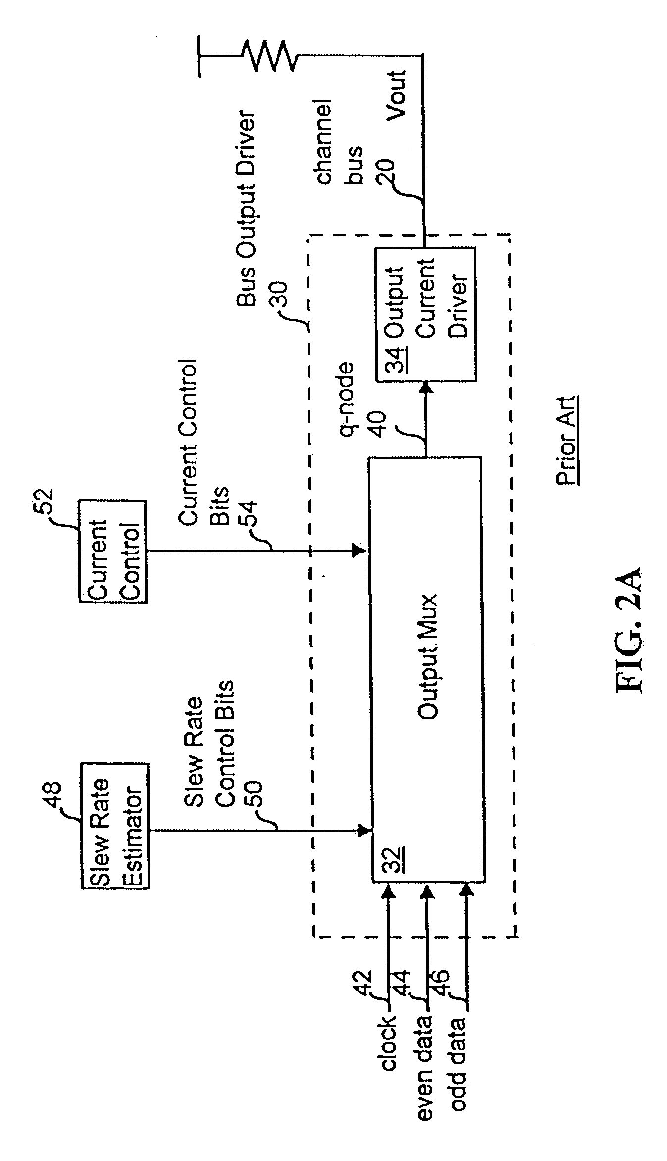
[0051] In FIG. 3, a bus output driver 120 has an output multiplexor 122 that connects to an output current driver 124 at a q-node 126. A clock signal, an even data signal, and an odd data signal are supplied to the output multiplexor 122 at a clock input 127, an even data input 128 and an odd data input 129, respectively. The output-multiplexor 122 outputs a q-node signal on the q-node 126 that is used to control the slew rate and output impedance of a channel signal, Vout. In response to the q-node signal, the output current driver 124 outputs the channel signal, Vout, on the channel 130 of the bus. A V-gate supply block 132 supplies control signals and a V-gate voltag; to the output multiplexor 122 and will be discussed in detail below. In another embodiment, the V-gate supply block 132 is not used.

[0052] The output multiplexor 122 is responsive to a slew rate control signal, consisting of slew rate control (SRC) bits 135, received from a slew rate estimator, which may be externa...


PUM


Abstract

An output driver has an output multiplexor and an output current driver. The output multiplexor receives a data signal and outputs a q-node signal. The output current 5 river receives the q-node signal and drives a bus based on the q-node signal. The output multiplexor processes the data signal in various ways to generate the q-node signal. The output current driver is responsive to current control bits to select a amount of output drive current. In addition, the output multiplexor is controlled such that the output impedance of the output current driver is maintained within a predetermined range.

Description

RELATED APPLICATIONS [0001] This application is a continuation application of application Ser. No. 10 / 731,718 filed on Dec. 8, 2003 which is a continuation of application Ser. No. 10 / 014,650 filed on Dec. 11, 2001 which is now U.S. Pat. No. 6,661,268 issued Dec. 9, 2003, which is a continuation of application Ser. No. 09 / 698,997 filed on Oct. 26, 2000 which is now U.S. Pat. No. 6,342,800 issued Jan. 29, 2002, which is a continuation of application Ser. No. 09 / 222,590 filed on Dec. 28, 1998 which is now U.S. Pat. No. 6,163,178 issued Dec. 19, 2000 all of which are hereby incorporated by reference.BACKGROUND OF THE INVENTION [0002] The present invention relates generally to an output driver for integrated circuits, and more specifically to an apparatus and method for a bus output driver for integrated circuits. [0003] Integrated circuits connect to and communicate with each other. Typically, integrated circuits communicate with each other using a bus with address, data and control sig...

Claims


Application Information

Patent Timeline
Patent Type & Authority Applications(United States)
IPC IPC(8): G11C7/10H03B1/00H03K17/16H03K19/003
CPCG11C7/1051H03K19/00384H03K17/164
Inventor STARK, DONALD C.KIM, JUNKNORPP, KURT T.CHING, MICHAEL TAK-KEIKUSHIYAMA, NATSUKI
Owner RAMBUS INC
Learn More