Self contained keypad assembly

a keypad and self-contained technology, applied in the field of keypad assemblies, can solve the problems of adversely affecting the functionality of the electronic unit, the general vulnerability of the electronic unit to damage, and the assembly cost of the hand-held mobile terminal, so as to reduce the cost and mechanical overhead, facilitate field operation, and mitigate the effect of damag

Active Publication Date: 2005-10-27
SYMBOL TECH LLC
View PDF14 Cites 5 Cited by
  • Summary
  • Abstract
  • Description
  • Claims
  • Application Information

AI Technical Summary

Benefits of technology

[0008] The present invention provides for systems and methods of supplying a self contained key pad assembly that is over molded around a boundary defined by and / or common to a top cover and a bottom cover, wherein the top cover and the bottom cover encapsulate a plurality of key pad components packed together. Such over molding around the pack of keypad components can create a protective seal against outside contaminants and mitigate damage thereto. Moreover, the encapsulating arrangement of the present invention can reduce costs and mechanical overheads associated with holding the various key pad components in place.
[0009] According to one aspect of the present invention, a replaceable keypad unit is provided with a top cover and a bottom cover such that the top cover and the bottom cover encapsulate and / or sandwich a stack of keypad components. The top cover and bottom cover can define and / or connect along a boundary (e.g. a common perimeter, common surface, contact area, edge(s) of the stack, and the like) that is subsequently over molded to create a sealed key pad assembly unit. The packed stack between the top cover and the bottom cover can include a printed circuit board with flex member, an electro luminous panel, and a silicone membrane with a plurality of keys thereupon. The top cover can include a plurality of orifices wherein the keys poke there through. Such stand alone key pad assembly unit, when incorporated into an electronic device can facilitate field operation (e.g., provide ease of replacement for the keypad unit, mitigate environmental contamination, and the like.) In addition, the stand alone key pad manufactured by over molding a top cover and a bottom cover is typically sized smaller than prior art modules, and provides for a configuration that reduces its damage susceptibility during application in harsh environments.
[0010] Such stand alone key pad unit can also facilitate modular fabrication, as it can be readily mounted on a host unit after assembling the host unit. The outer side of the keypad's bottom cover (the side facing the host unit) can include additional bonding posts and pins as to improve bonds formed between the self contained key pad assembly and the host unit. Such side can further comprise interconnect pins and electrical connections employed for subsequent wire bonding and coupling of the stand alone keypad to the host electronic device.
[0011] In a related aspect of the present invention, the flex member, which can be an extension of a flexible printed circuit board, provides an electrical connection between the self contained key pad unit and the host device. Moreover, the flex member can over hang from the bottom cover, and can further employ an adhesive to connect thereto. The flex member can include exposed contacts to mate with host terminals. Such flex member can protrude out a trough of the over molded key pad. A wide flex radius provided on the flex member can allow for a range of flexural bending and twisting along the edges of the keypad compartment without breakage of the flex member. As such, the flex member can be aligned and accepted with improved connectivity for subsequent attachment via openings in a circuit board or other components adapted for receiving the keypad. This further mitigates rupture of flex components during assembly operation. In addition, a key pad fabricated with such flexes facilitates any required sealing and provides improved electrostatic discharge protection for the electronic device. Also, because of the over molding of the present invention, virtually the entire body of the self contained key pad can be plastic, wherein the individual power pins and interconnects can be located in close proximity, since plastic of the over mold can provide a higher dielectric insulation as compared to the more conventional use of air as a dielectric insulator.

Problems solved by technology

In particular, many electronic units such as hand hold mobile terminals, communication units, and the like have various assembly costs, and are generally susceptible to damage during employment in harsh environments.
Because the key switches consist of a number of parts, and are respectively placed in their respective position on the frame, gaps can exist in the common boundaries through which external environmental contaminants (e.g., water) can pass to the inside of the key pad assembly, and adversely affect its functionality.
In addition, in fabrication of such key pad assembly there are costs associated with various mechanical overheads for holding a plurality of key pad components in place.
Moreover, a typical assembly of such key pad components into a compartment that houses the electronic unit can require several manufacturing processes.
Such assembly steps are generally time consuming and expensive in manufacturing.

Method used


Image

  • Self contained keypad assembly
  • Self contained keypad assembly
  • Self contained keypad assembly

Examples


Embodiment Construction

[0023] The present invention is now described with reference to the drawings, wherein like reference numerals are used to refer to like elements throughout. In the following description, for purposes of explanation, numerous specific details are set forth in order to provide a thorough understanding of the present invention. It may be evident, however, that the present invention may be practiced without these specific details. In other instances, well-known structures and devices are shown in block diagram form in order to facilitate describing the present invention.

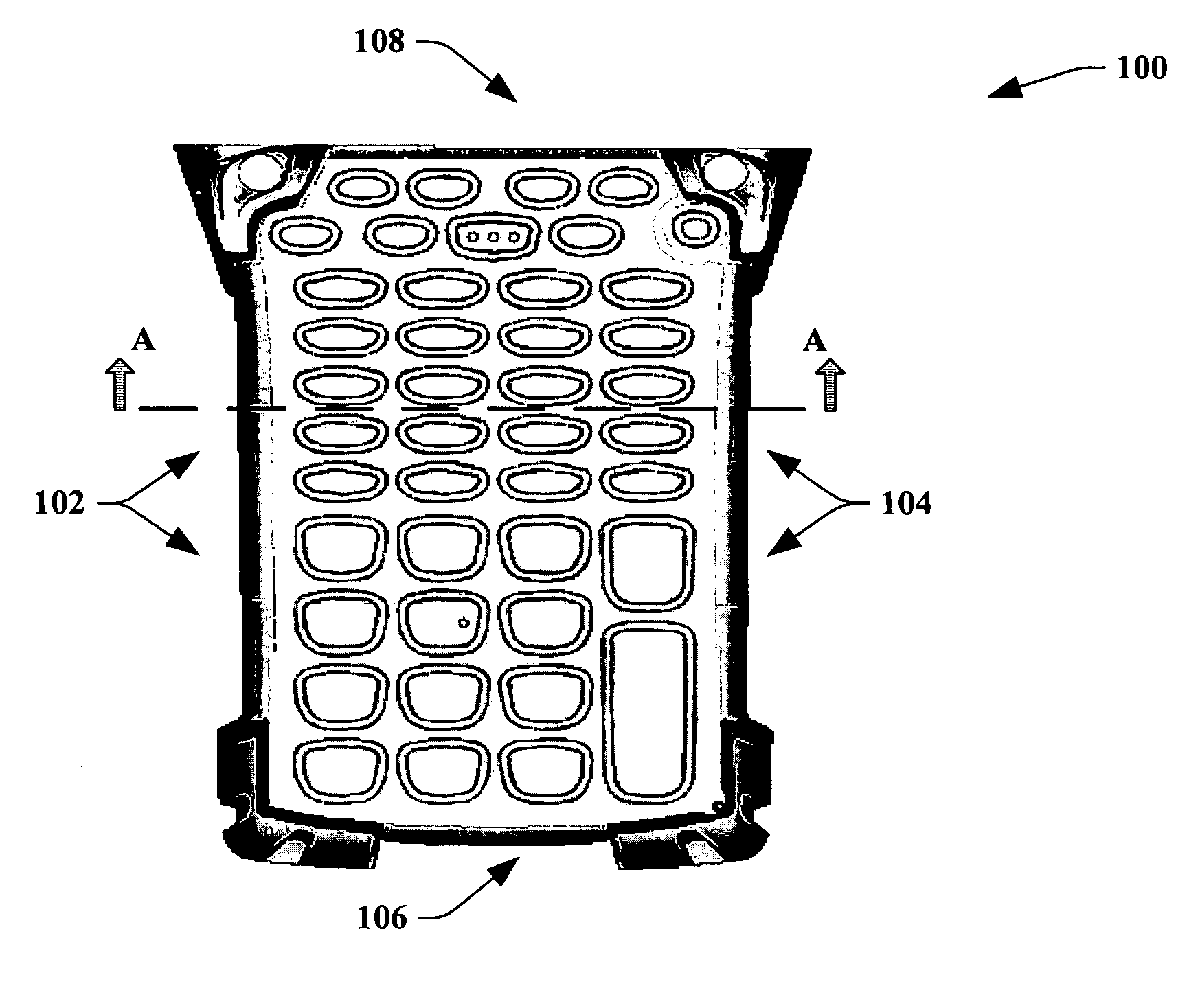
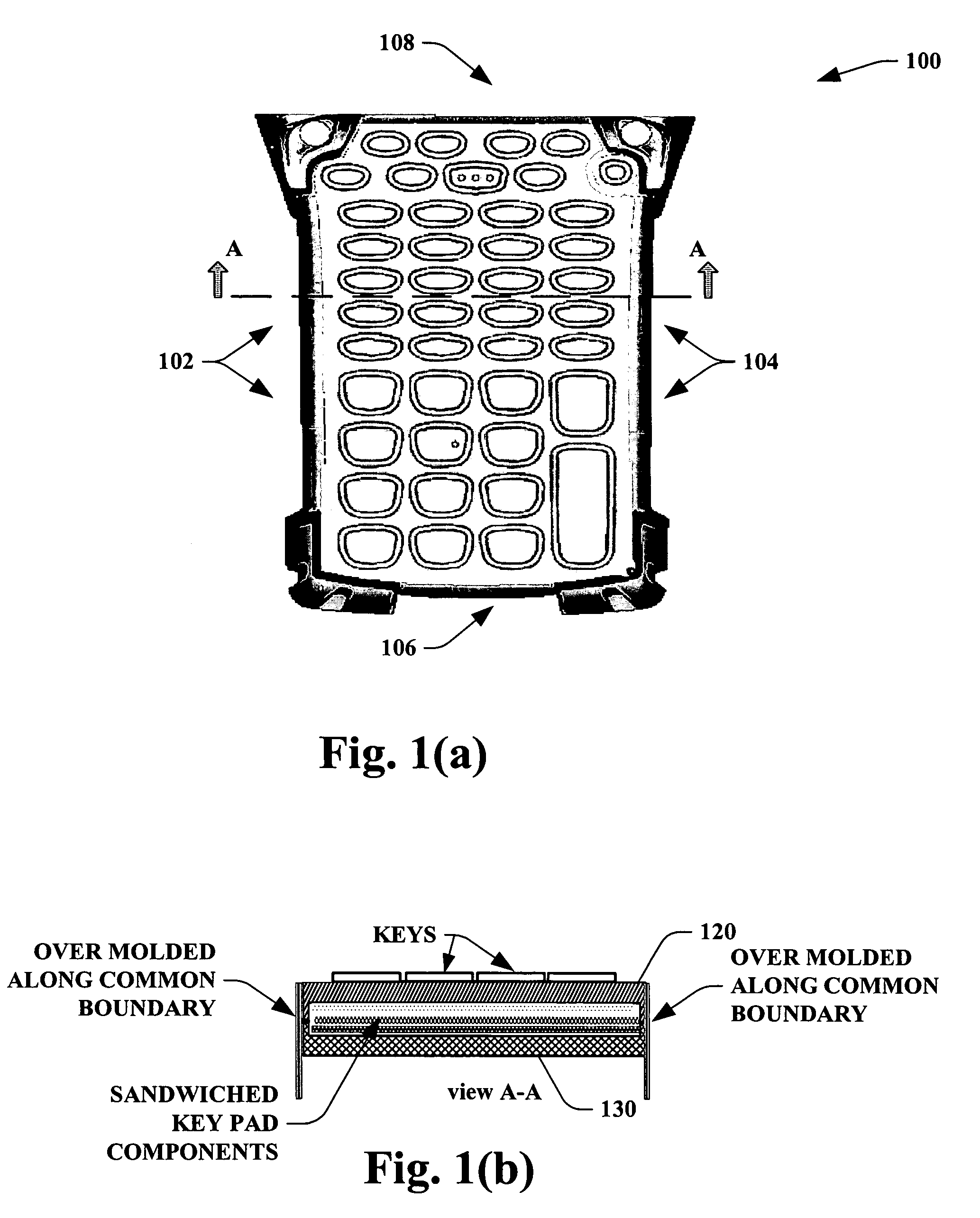
[0024] The present invention provides for systems and methods of supplying a self contained key pad assembly that mitigates mechanical over head associated with holding various key pad components, while providing for a configuration that reduces its damage susceptibility during application in harsh environments. Referring initially to FIGS. 1(a) and 1(b), a plan view and a schematic side view cut of a stand alone and se...


PUM

PropertyMeasurementUnit
brightnessaaaaaaaaaa
electrical connectionsaaaaaaaaaa
perimeteraaaaaaaaaa

Abstract

Systems and methodologies are provided for fabrication of a self contained key pad module having a top cover and a bottom cover. The top cover and the bottom cover encapsulate and / or sandwich a stack of keypad components via an over mold procedure that is performed around the stack. The packed stack between the top cover and the bottom cover can include a flex member, an electro luminous panel, and a silicone membrane with a plurality of keys thereupon.

Description

TECHNICAL FIELD [0001] The present invention relates generally to key pad assemblies, and more particularly to systems and methods that provide for a top cover and bottom cover being over molded around an entire common boundary therebeween, to encapsulate various key pad components. BACKGROUND OF THE INVENTION [0002] Typically there is a desire to reduce size of electronic units, while lowering associated assembly costs and improving overall ruggedness. In particular, many electronic units such as hand hold mobile terminals, communication units, and the like have various assembly costs, and are generally susceptible to damage during employment in harsh environments. Such units are generally assembled by enclosing internal electrical components, such as key pads, a central processing unit (CPU) board, display, and internal wiring, within a housing made of plastic or another structural material. [0003] In general, the key pad for such electronic apparatus is comprised of a circuit boa...

Claims


Application Information

Patent Timeline
Patent Type & Authority Applications(United States)
IPC IPC(8): G06F3/02B29C45/14H01H13/70H01H13/702H03M11/00
CPCB29C45/14639B29L2031/466H01H13/702H01H2207/004H01H2207/01H01H2217/033H01H2239/056H01H2219/039H01H2223/002H01H2229/048H01H2239/008H01H2239/048H01H2219/018H01H13/48H01H13/704H01H13/705H04M1/22H04M1/23
Inventor GONG, FRANKCROLEY, CURT D.GARCIA, JOSEPH JR.
Owner SYMBOL TECH LLC
Why Eureka
Try Eureka