Wavelength conversion module

a conversion module and wavelength technology, applied in the direction of light demodulation, instruments, laser details, etc., can solve the problems of unstable output of shg laser modules and inability to realize suitable laser modules

Active Publication Date: 2005-10-27
FURUKAWA ELECTRIC CO LTD
View PDF11 Cites 10 Cited by
  • Summary
  • Abstract
  • Description
  • Claims
  • Application Information

AI Technical Summary

Benefits of technology

[0011] It is an object of the present invention to provide an SHG laser module with stable outputs or an SHG laser module which can cause co

Problems solved by technology

However, the above-described conventional technique has a problem such that the YAG crystal 21 is heated when the fundamental is emitted by laser oscillation and the wavelength of light emitted from

Method used


Image

  • Wavelength conversion module
  • Wavelength conversion module
  • Wavelength conversion module

Examples


first embodiment

[0049] In a first embodiment, EBG is used as an external resonator in order to stabilize an oscillation wavelength of a semiconductor laser module.

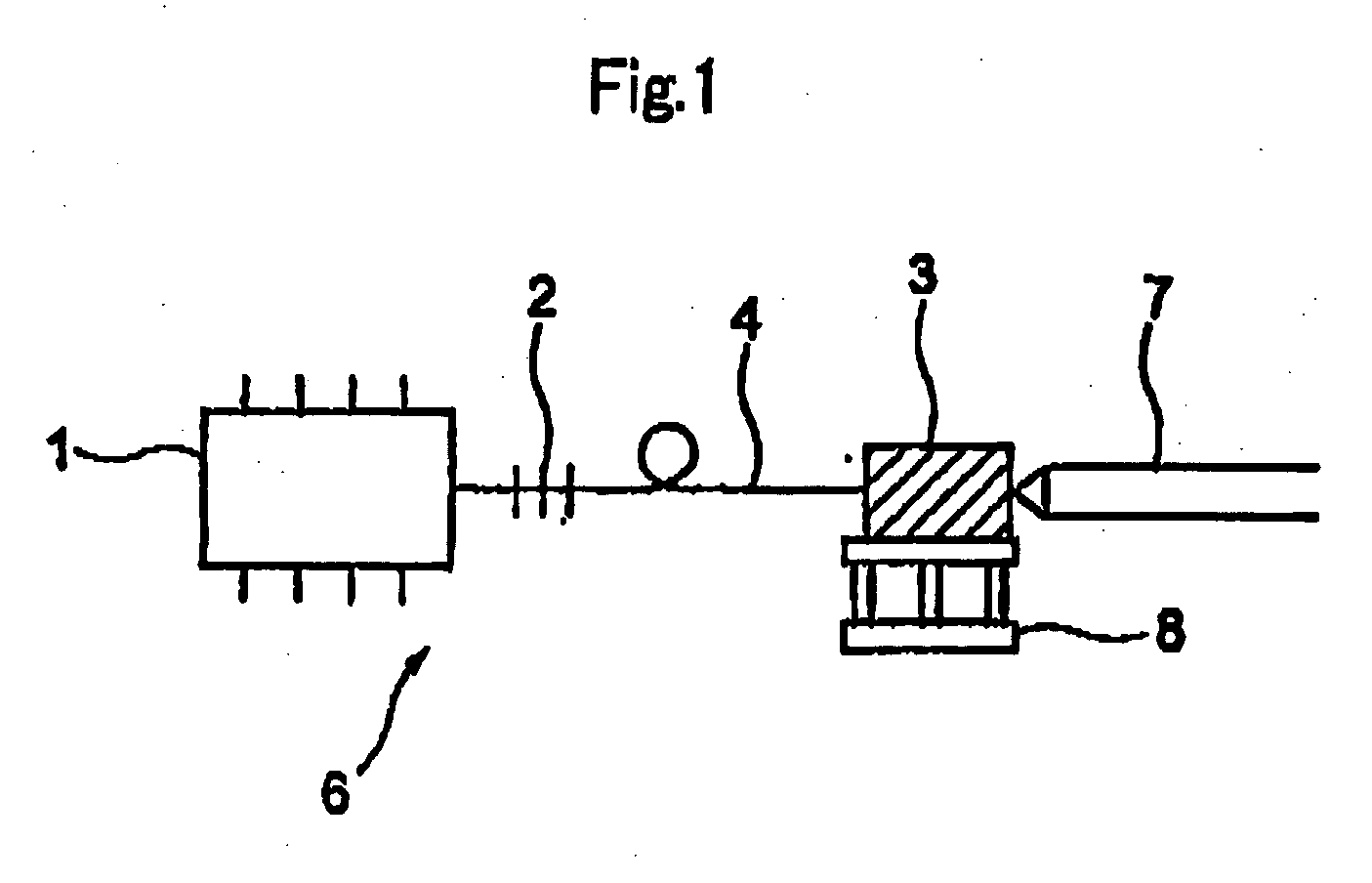
[0050]FIG. 1 shows a wavelength conversion laser module 6 according to the embodiment of the present invention. A semiconductor laser module 1 and a wavelength conversion device 3 are coupled by a polarization maintaining optical fiber 4 which has a FBG 2. A wavelength of light output from the semiconductor laser module 1 is fixed at one longitudinal mode by the FBG 2.

[0051] In order to change an output from the wavelength conversion laser module 6, a driving current of the semiconductor laser module 1 is changed. Even when the driving current is changed, the wavelength is not shifted since the wavelength is fixed by the FBG 2. Accordingly, it is possible to achieve stable change in an output from the wavelength conversion laser module 6.

[0052] Since the wavelength conversion device 3 has polarization dependence, a polarization maintai...

example 1

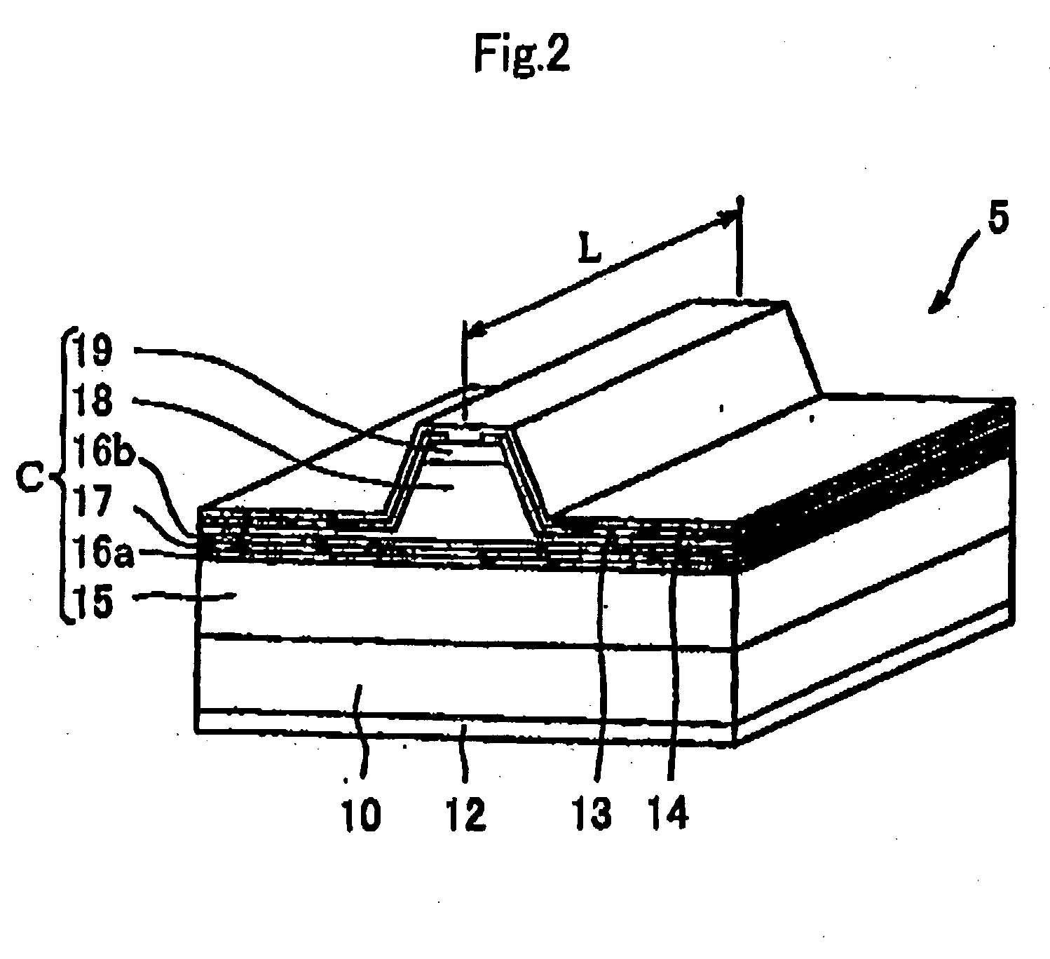
[0055]FIG. 2 shows a semiconductor laser element 5 used in the example 1. The semiconductor laser element 5 is structured by laminating on a GaAs substrate 10 a lower cladding layer 15 of AlGaAs, a lower GRIN-SCH layer 16a of AlGaAs, an active layer 17 having a quantum well structure, an upper GRIN-SCH layer 16b of AlGaAs, a upper cladding layer 18 of AlGaAs, and a cap layer 19. The symbol 12 depicts a lower electrode and the symbol 14 depicts an upper electrode. A well layer of the quantum well active layer 17 is made of InGaAs.

[0056] The wavelength of light output from the semiconductor laser element 5 was 976 nm. This semiconductor laser element 5 is incorporated in the semiconductor laser module 1 shown in FIG. 1 to build the wavelength conversion laser module 6.

[0057] The wavelength of light output from the wavelength conversion device 3, or the wavelength of light output from the wavelength conversion laser module 6, was 488 nm.

example 2

[0058] The semiconductor laser element 5 of the example 2 is structured in the same way as that of the example 1 except that the In composition of the well layer material InGaA is changed. The wavelength of light output from the semiconductor laser element 5 was 1,064 nm.

[0059] The wavelength conversion laser module 6 of the example 2 has the same structure as that of the example 1. The wavelength of light output from the wavelength conversion device (SHG device) 3, or the wavelength of light output from the wavelength conversion laser module 6, was 532 nm.


PUM


Abstract

A wavelength conversion module according to the present invention includes an external resonator, a semiconductor laser module and a wavelength conversion device for converting a wavelength of light output from the semiconductor laser module into a shorter wavelength. This wavelength conversion device includes at least one of a nonlinear crystal for generating SFG (Sum-frequency Generation) light and a nonlinear crystal for generating SHG (Second Harmonic Generation) light. Each of the SFG generating element and the SHG generating element of the wavelength conversion device may have a periodically-poled ridge-waveguide structure or a periodically-poled proton-exchanged-waveguide structure.

Description

TECHNICAL FIELD [0001] The present invention relates to stabilization of intensity of light output from an SHG (Second Harmonic Generation) laser module and an SFG (Sum-frequency Generation) laser module. BACKGROUND ART [0002] Light output from a GaAs semiconductor laser has a wavelength which covers from around 1 μm to the 600 nm range, while a GaN semiconductor laser has been developed to output light with a wavelength of 405 nm mainly for use of next generation DVD light source. Well known as a laser of wavelength between them, that is, between about 400 nm and the 600 nm range are an Ar laser (488 nm / 515 nm) and a combination of YAG / YLF and SHG (532 nm), for example. [0003] The combination of YAG / YLF and SHG (532 nm) is developed for high power use (W level) and the YAG / YLF and SHG market is rapidly expanded in the fields of a marker of Si board or the like and trimming or repairing of TFT liquid crystal. Particularly, since a “marker” is now in increasing demand because of expa...

Claims


Application Information

Patent Timeline
IPC IPC(8): G02F1/35G02F1/37
CPCG02F1/3534G02F2201/02G02F2001/3548G02F1/37G02F1/3548
Inventor OHKUBO, MICHIOMATSUURA, HIROSHI
Owner FURUKAWA ELECTRIC CO LTD
Why Eureka
Try Eureka