Filtering image data to obtain samples mapped to pixel sub-components of a display device

a display device and image data technology, applied in image enhancement, image analysis, instruments, etc., can solve the problems of luminance accuracy, color errors or lowered resolution, etc., and achieve the effects of reducing color aliasing, reducing color aliasing, and increasing cutoff frequency

Inactive Publication Date: 2005-10-27
MICROSOFT TECH LICENSING LLC
View PDF10 Cites 14 Cited by
  • Summary
  • Abstract
  • Description
  • Claims
  • Application Information

AI Technical Summary

Benefits of technology

[0013] The image processing methods of the invention can include a scaling operation, whereby the image data is scaled in preparation for subsequent oversampling, and a hinting operation, which can be used to adapt the details of an image to the particular pixel sub-component positions of a display device. The image data signal, which can have three channels, each representing a different color component of the image, is passed through a low-pass filter to eliminate frequencies above a cutoff frequency that has been selected to reduce color aliasing that would otherwise be experienced. Although the pixel Nyquist frequency can be used as the cutoff frequency, it has been found that a higher cutoff frequency can be used. The higher cutoff frequency yields greater sharpness, at some sacrifice of color aliasing.

Problems solved by technology

It has been found that mapping point samples or samples generated from a simple box filter directly to pixel sub-components results in either color errors or lowered resolution.
Moreover, it has been found that there is an inherent tradeoff between improving color accuracy and improving luminance accuracy.

Method used


Image

  • Filtering image data to obtain samples mapped to pixel sub-components of a display device
  • Filtering image data to obtain samples mapped to pixel sub-components of a display device
  • Filtering image data to obtain samples mapped to pixel sub-components of a display device

Examples


Embodiment Construction

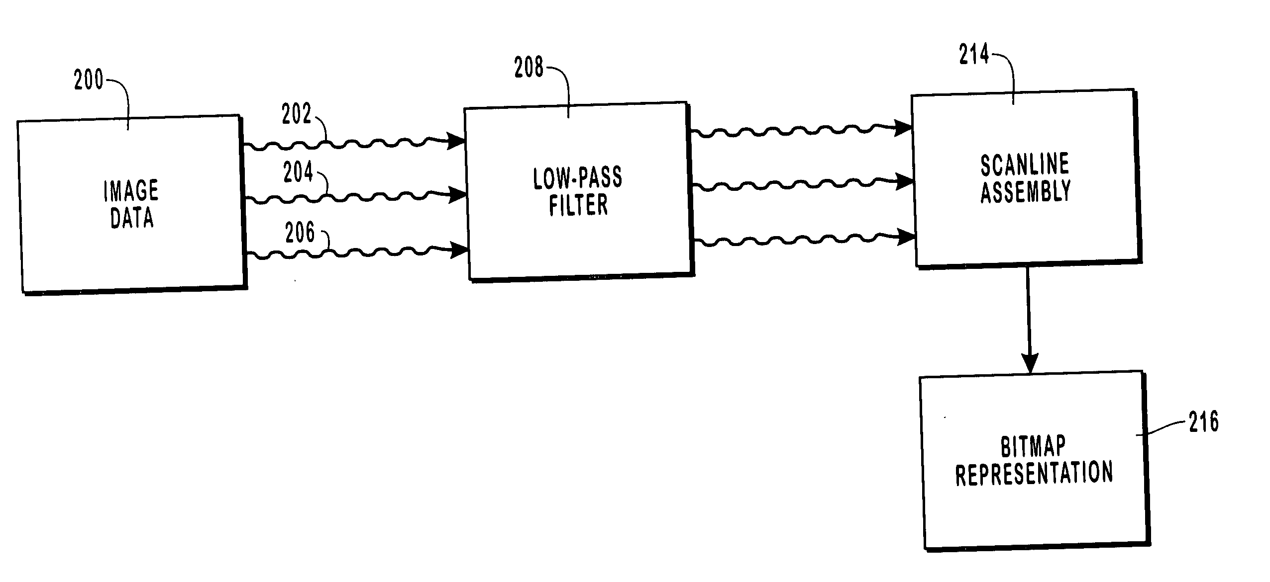
[0026] The present invention relates to image data processing and image rendering techniques whereby image data is rendered on patterned flat panel display devices that include pixels each having multiple separately controllable pixel sub-components of different colors. When applied to display devices, such as conventional liquid crystal display (LCD) devices, the image data processing operations include filtering a three-channel continuous signal representing the image data through filters that obtain samples that are mapped to the red, green, and blue pixel sub-components. The filters are selected to establish a desired tradeoff between color accuracy and luminance accuracy. Generally, an increase in color accuracy results in a corresponding decrease in luminance accuracy and vice versa. The samples mapped to the pixel sub-components are used to generate luminous intensity values for the pixel sub-components.

[0027] The image rendering processes are adapted for use with LCD device...


PUM


Abstract

Image data processing and image rendering methods and systems whereby images are displayed on display devices having pixels with separately controllable pixel sub-components. Image data, such as data encoded in a three-channel signal, is passed through a low-pass filter to remove frequencies higher than a selected cutoff frequency, which obtain samples from the color components of the signal that map spatially different image regions to individual pixel sub-components. It has been found that color aliasing effects can be significantly reduces at a cutoff frequency somewhat higher than the Nyquist frequency, while enhancing the spatial resolution of the image. The image data is then passed through sampling filters, A generalized set of filters includes nine filters, one for each combination of one color and one pixel sub-component. The filtering coefficients of the filters can be selected to optimize of approximate an optimization of an error metric, which represents the color and luminance errors perceived on the display device. In this manner, a desired balance between color accuracy and luminance accuracy can be obtained. The samples mapped to individual pixel sub-components are used to generate luminous intensity values for the displayed image.

Description

BACKGROUND OF THE INVENTION CROSS REFERENCE TO RELATED APPLICATIONS [0001] This application claims the benefit and priority of U.S. patent application Ser. No. 09 / 481,163, entitled “Filtering Image Data to Obtain Samples Mapped to Pixel Sub-Components of a Display Device,” filed Jan. 12, 2000, which claims the benefit of U.S. Provisional Patent Application Ser. No. 60 / 115,573, entitled “Resolution and Image Enhancement for Patterned Displays,” filed Jan. 12, 1999 and U.S. Provisional Patent Application Ser. No. 60 / 115,731, entitled “Resolution Enhancement for Patterned Displays,” filed Jan. 12, 1999. U.S. patent application Ser. No. 09 / 481,163 also being a continuation-in-part of U.S. patent application Ser. No. 09 / 364,365, entitled “Methods, Apparatus and Data Structures for Enhancing the Resolution of Images to be Rendered on Patterned Display Devices,” filed Jul. 30, 1999. The pending application incorporates by reference and claims the benefit and priority of all of the foregoin...

Claims


Application Information

Patent Timeline
Patent Type & Authority Applications(United States)
IPC IPC(8): G06T5/20G06KG06K9/00G06K9/40G06T1/00G06T5/00G06T7/40G09G3/20G09G3/36G09G5/00G09G5/28H04N1/409H04N1/46H04N1/60
CPCG09G5/005G09G5/006G09G2340/0457G09G2320/0276G09G2320/0242
Inventor PLATT, JOHN C.MITCHELL, DONALD P.WHITTED, J. TURNERBLINN, JAMES F.
Owner MICROSOFT TECH LICENSING LLC
Why Eureka
Try Eureka