Eureka AIR delivers breakthrough ideas for toughest innovation challenges, trusted by R&D personnel around the world.

Image forming apparatus

a technology of image forming apparatus and forming apparatus, which is applied in the direction of electrographic process apparatus, instruments, optics, etc., can solve the problems of over-described full-color image forming apparatus, which tends to become bulky, and achieves the effect of reducing the size of the image forming apparatus and speeding up the process

Inactive Publication Date: 2005-10-27
CANON KK
View PDF6 Cites 0 Cited by
  • Summary
  • Abstract
  • Description
  • Claims
  • Application Information

AI Technical Summary

Benefits of technology

[0010] It is an object of the present invention to provide an image forming apparatus which can make both of the higher speed of image forming and the downsizing of the image forming apparatus compatible.
[0011] It is another object of the present invention to provide an image forming apparatus which can make both of a higher quality of image in image forming and the downsizing of the image forming apparatus compatible.
[0012] It is another object of the present invention to provide an image forming apparatus in which a plurality of developer carrying members can be accurately positioned relative to an image bearing member by a simple construction.

Problems solved by technology

The above-described full-color image forming apparatus, however, tends to become bulky and has posed a problem in this point.

Method used


Image

  • Image forming apparatus
  • Image forming apparatus
  • Image forming apparatus

Examples


Embodiment Construction

[0020] Some embodiments of the present invention will hereinafter be described with reference to the drawings.

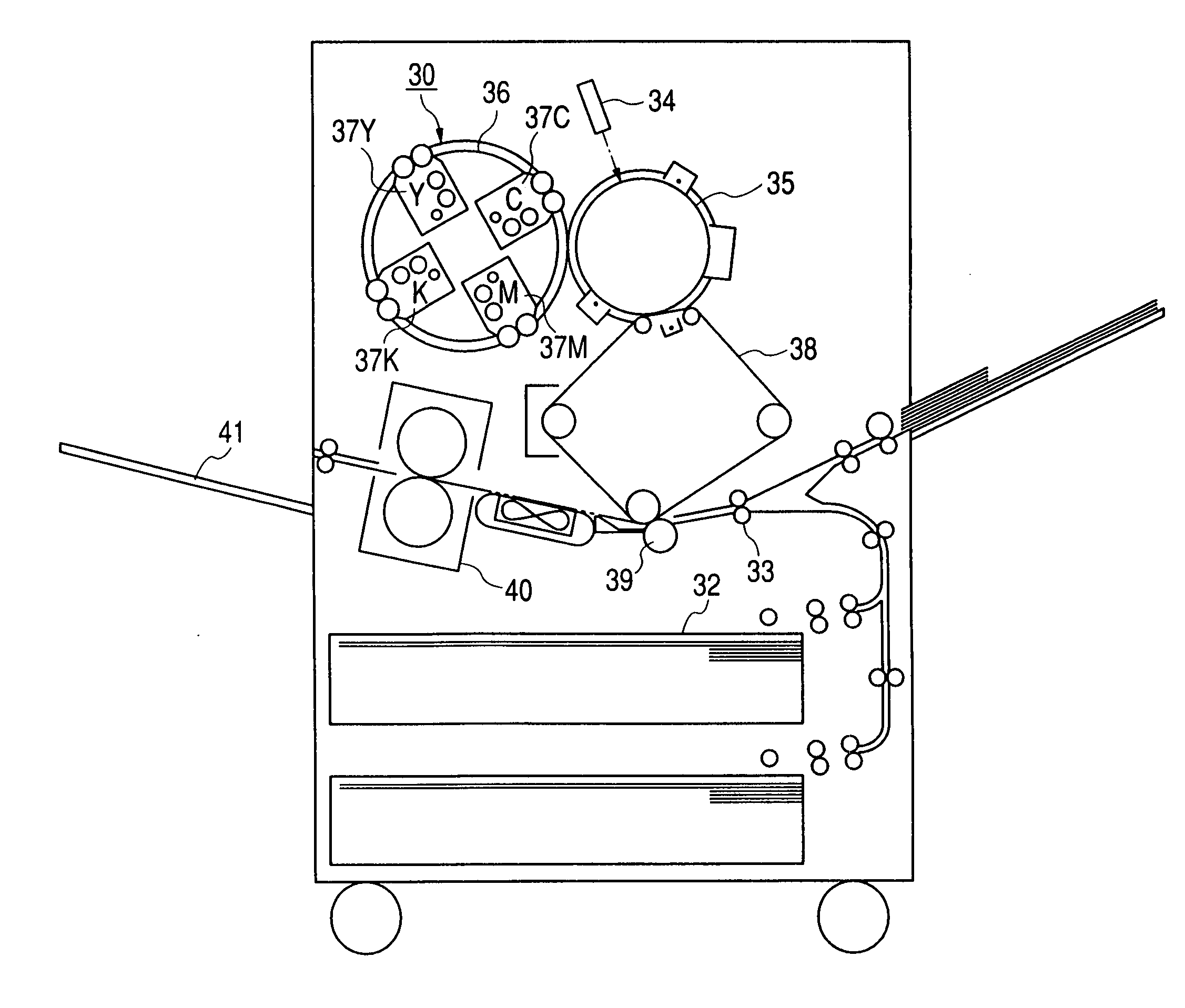
[0021]FIG. 1 is a schematic cross-sectional view of a full-color printer provided with a developing apparatus according to the present invention.

[0022] In the full-color printer of FIG. 1, the image information of an original read by an image reading portion (not shown) is processed by an image processing portion (not shown). For example, a recording sheet (not shown) fed from a cassette sheet feeding portion 32 has its skew feeding corrected at a registering portion 33 and comes to a secondary transferring portion 39.

[0023] On the other hand, the image data processed by the image processing portion (not shown) is recorded as a latent image on a photosensitive drum 35 by a laser scanner portion 34. When a full-color image is to be formed, the latent image is developed by a rotary type developing apparatus 30. Here, the rotary type developing apparatus 30 develops the late...


PUM


Abstract

An image forming apparatus includes a photosensitive drum, a charging roller, a transfer roller, and a toner charging brush, wherein the toner charging brush reciprocates in a longitudinal direction of the photosensitive drum. In the image forming apparatus, when a number of rotations per a unit time of the image bearing member is assumed to be “a” and a number of times of reciprocation per unit time of the toner charging brush is assumed to be “b” assuming that R=b / a, R is set to be in a range of 1 / 25≦R≦3. However, R=m / n (m and n are integers of 5 or less) is excluded. Consequently, generation of a periodic attachment pattern appearing on the photosensitive drum is eliminated.

Description

BACKGROUND OF THE INVENTION [0001] 1. Field of the Invention [0002] The invention relates to an image forming apparatus adopting an electrophotographic process or an electrostatic recording process, and particularly to an image forming apparatus such as a copying machine, a printer or a facsimile apparatus. [0003] 2. Description of Related Art [0004] In an image forming portion in an image forming apparatus such as a copying machine, a photosensitive member which is an image bearing member is charged by a charging apparatus, and is exposed to the image of an original at an exposure position by an exposing optical system to thereby form an electrostatic latent image on the peripheral surface of the photosensitive member, and this electrostatic latent image is developed by a developing apparatus to thereby form a developer image (toner image), and this toner image is transferred to a transferring material by the application of a voltage by a transferring apparatus, and the photosensit...

Claims


Application Information

Patent Timeline
Patent Type & Authority Applications(United States)
IPC IPC(8): G03G15/01G03G21/00G03G15/08
CPCG03G15/0126G03G2215/0177G03G15/0896
Inventor IKEDA, TAROSEKINE, HIROYUKI
Owner CANON KK
Why Eureka
Eureka Blog
Learn More