Methods of forming integrated circuit devices having field effect transistors of different types in different device regions

a field effect transistor and integrated circuit technology, applied in the field of semiconductor devices, can solve the problems of short channel, channel region may not achieve a complete depletion state, and may be more susceptible to short channel effects

Active Publication Date: 2005-10-27
SAMSUNG ELECTRONICS CO LTD
View PDF8 Cites 79 Cited by
  • Summary
  • Abstract
  • Description
  • Claims
  • Application Information

AI Technical Summary

Problems solved by technology

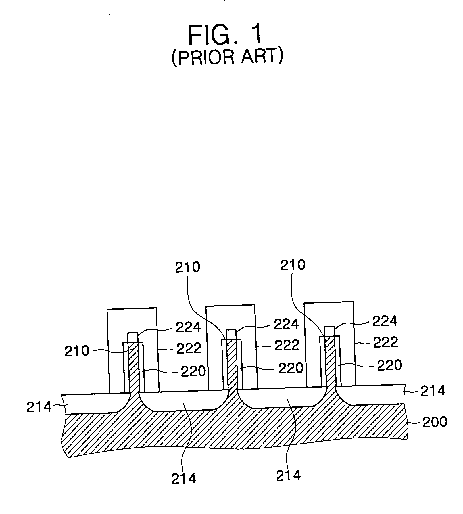
However, as transistor size decreases, a variety of problems may result, such as short channel effects.
For example, when the width of the channel region is more than twice the maximum depletion width for higher voltages, the channel region may not achieve a complete depletion state.
Accordingly, a FinFET may be more susceptible to short channel effects as the width of the channel region (and therefore, the height of the fin) is increased.

Method used


Image

  • Methods of forming integrated circuit devices having field effect transistors of different types in different device regions
  • Methods of forming integrated circuit devices having field effect transistors of different types in different device regions
  • Methods of forming integrated circuit devices having field effect transistors of different types in different device regions

Examples


Embodiment Construction

[0031] The present invention will be described more fully hereinafter with reference to the accompanying drawings, in which exemplary embodiments of the invention are shown. However, this invention should not be construed as limited to the embodiments set forth herein. Rather, these embodiments are provided so that this disclosure will be thorough and complete, and will fully convey the scope of the invention to those skilled in the art. In the drawings, the thickness of layers and regions are exaggerated for clarity. Like numbers refer to like elements throughout.

[0032] It will be understood that when an element such as a layer, region or substrate is referred to as being “on” or extending “onto” another element, it can be directly on or extend directly onto the other element or intervening elements may also be present. In contrast, when an element is referred to as being “directly on” or extending “directly onto” another element, there are no intervening elements present. It will...


PUM

PropertyMeasurementUnit
energy levelaaaaaaaaaa
energyaaaaaaaaaa
conductiveaaaaaaaaaa

Abstract

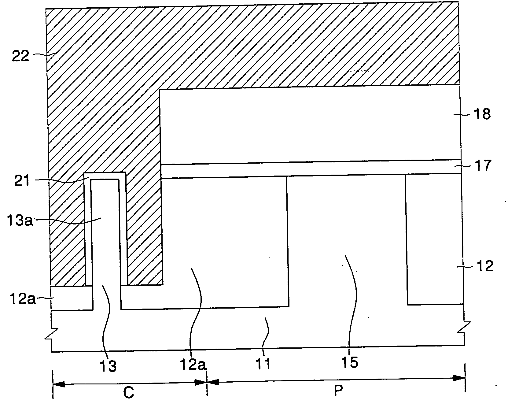
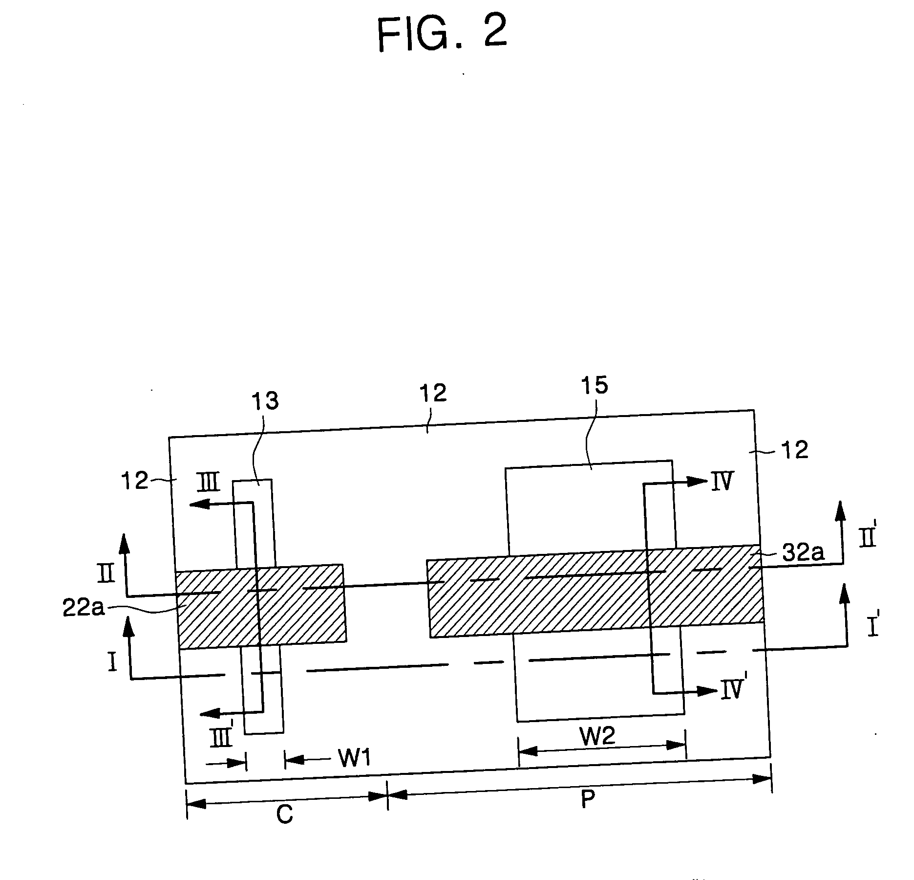
A method of forming an integrated circuit device includes forming a non-planar field-effect transistor in a cell array portion of a semiconductor substrate and forming a planar field-effect transistor in a peripheral circuit portion of the semiconductor substrate. The non-planar field-effect transistor may be selected from the group of a FinFET and a recessed gate FET. Dopants may be implanted into a channel region of the non-planar field-effect transistor, and a cell protection layer may be formed on the non-planar field-effect transistor. Then, dopants may be selectively implanted into a channel region of the planar field-effect transistor using the cell protection layer as a mask to block implanting of the dopants into the channel region of the non-planar field-effect transistor.

Description

CROSS-REFERENCE TO RELATED APPLICATION [0001] This application claims priority from Korean Patent Application No. 10-2004-0029118, filed Apr. 27, 2004, the contents of which are hereby incorporated by reference herein in their entirety. BACKGROUND OF THE INVENTION [0002] 1. Field of the Invention [0003] The present invention relates to semiconductor devices, and more particularly, to methods of forming field effect transistors on a semiconductor substrate. [0004] 2. Description of Related Art [0005] Due to demand for smaller and more power-efficient electronic devices, research on methods of increasing semiconductor device integration is actively being pursued. In order to reduce transistor size to meet these demands for higher device integration, increasingly fine transistor patterns may be required. However, as transistor size decreases, a variety of problems may result, such as short channel effects. As such, research is being conducted on fin field-effect transistors (FinFETs), ...

Claims


Application Information

Patent Timeline
Patent Type & Authority Applications(United States)
IPC IPC(8): H01L21/336H01L27/088H01L21/8232H01L21/8234H01L21/8239H01L29/786H01L31/0328
CPCH01L21/823412H01L21/823437H01L21/823456H01L27/1052H01L29/66621H01L29/66795H01L29/7851H01L21/823462H10B99/00B21C49/00B65H29/30
Inventor AHN, YOUNG-JOONPARK, DONG-GUNLEE, CHOONG-HOKANG, HEE-SOO
Owner SAMSUNG ELECTRONICS CO LTD
Why Eureka
Try Eureka