
Joystick controlled scrubber

a scrubber and joystick technology, applied in the direction of motor/generator/converter stopper, dynamo-electric converter control, transportation and packaging, etc., can solve the problems of unsafe condition of machine, inability to travel at high speed and turn the wheel, etc., to improve maneuverability, increase operator visibility, and improve traction

Active Publication Date: 2005-10-27
NILFISK
View PDF15 Cites 11 Cited by
  • Summary
  • Abstract
  • Description
  • Claims
  • Application Information

AI Technical Summary

Benefits of technology

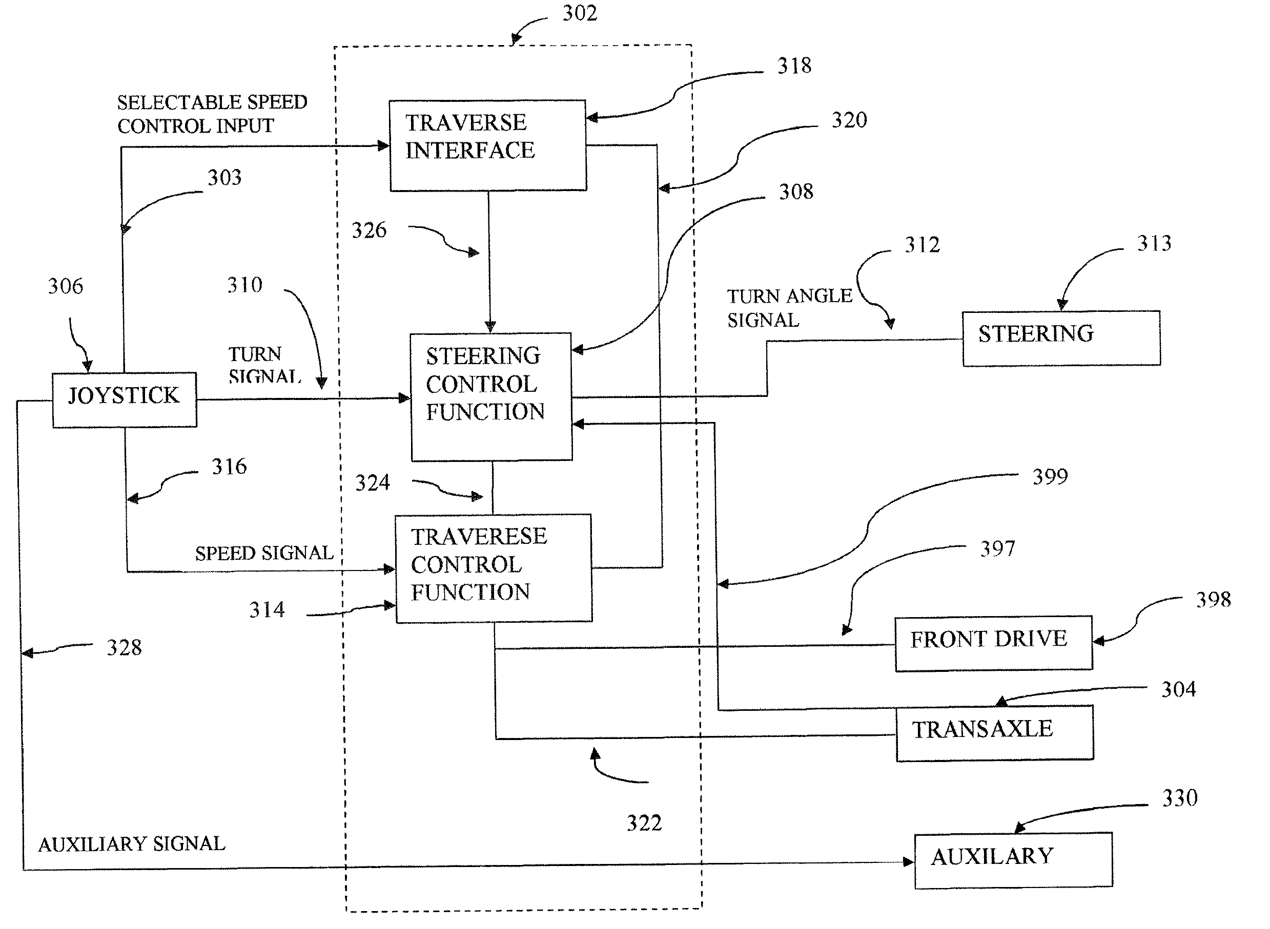
"The present invention is a floor maintenance vehicle with a joystick control system that integrates steering and speed control. The joystick control system provides better visibility and maneuverability compared to traditional steering wheel systems. The vehicle uses a transaxle drive system and a powered steering system for the front wheel, which improves traction and maneuverability. The speed and steering angle are tied together to prevent unsafe conditions. The invention combines the benefits of a steering system and a speed control system to provide improved visibility, maneuverability, operator comfort, traction, and control. It is easy to drive, train, and maintain, and is more conducive for people with disabilities. The invention incorporates all machine movement control into one device."

Problems solved by technology

This system makes it impossible to travel at high speed and turn the wheel to its sharpest turning point, placing the machine in an unsafe condition.

Method used


Image

  • Joystick controlled scrubber
  • Joystick controlled scrubber
  • Joystick controlled scrubber

Examples


Embodiment Construction

[0022] According to the embodiment(s) of the present invention, various views are illustrated in FIG. 1-3 and like reference numerals are being used consistently throughout to refer to like and corresponding parts of the invention for all of the various views and figures of the drawing. Also, please note that the first digit(s) of the reference number for a given item or part of the invention should correspond to the Fig. number in which the item or part is first identified.

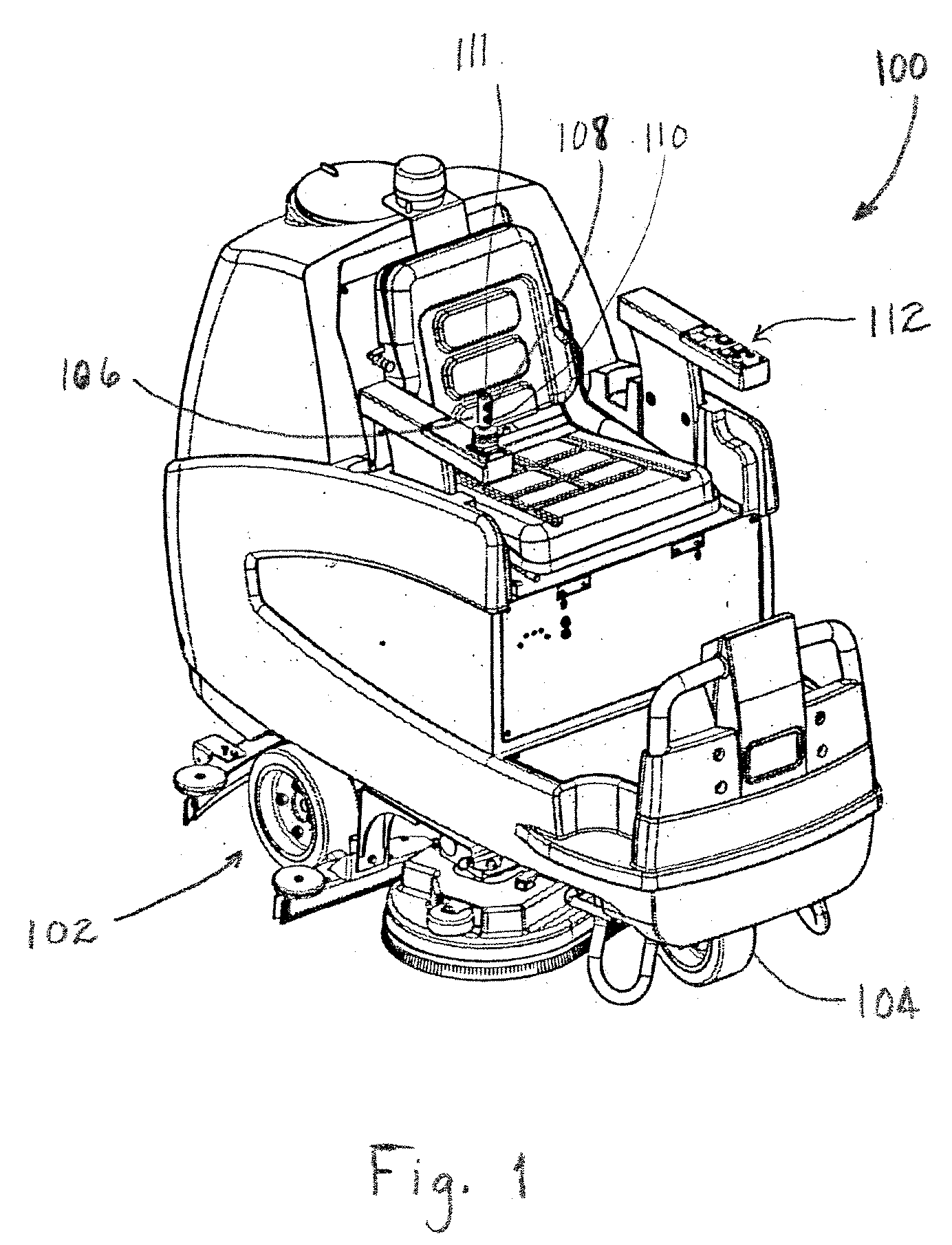
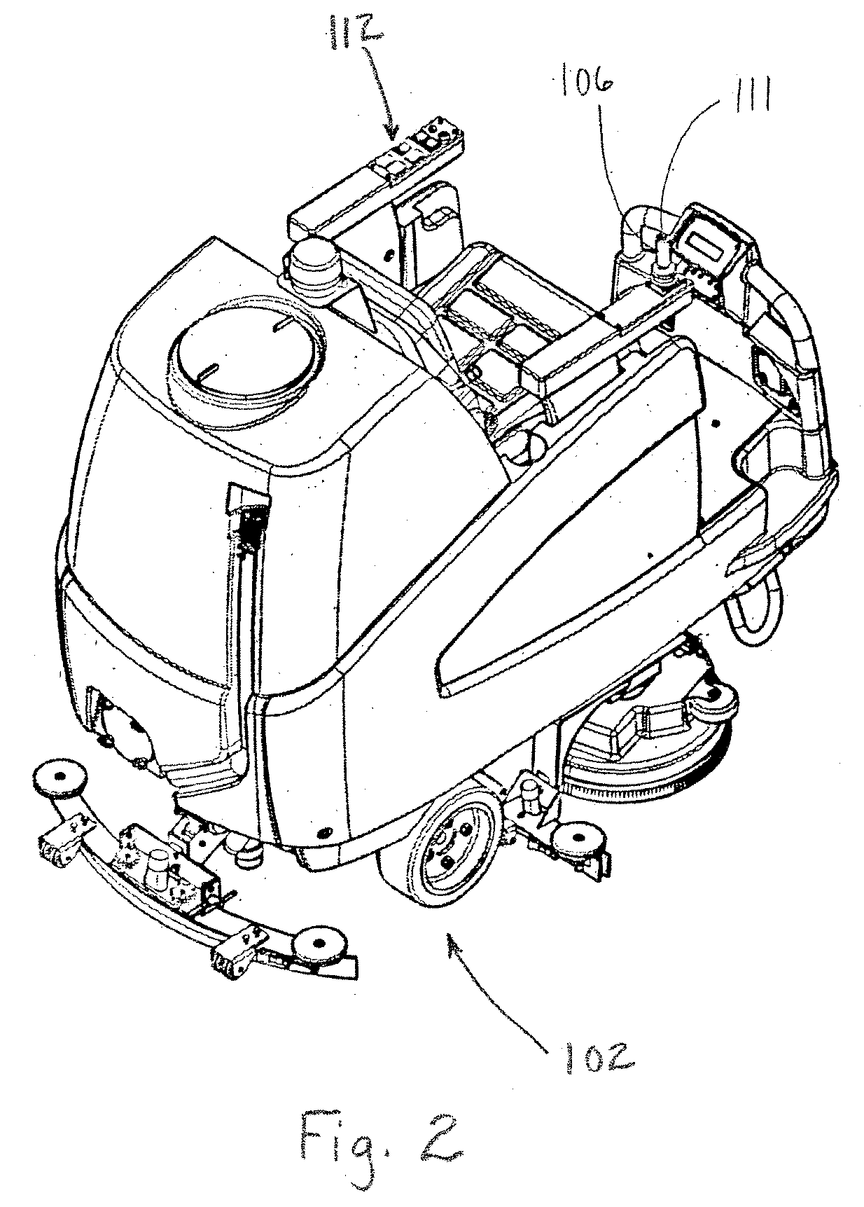
[0023] The details of the invention and various embodiments can be better understood by referring to the figures of the drawing. Referring to FIGS. 1 and 2, one embodiment of the present floor maintenance vehicle 100 invention comprising a transaxle rear drive system 102 and a powered steering system for controlling steering of a front wheel 104; and a joystick control system for providing integrated control of the transaxle rear drive system and the powered steering system by controlling the traverse output of ...


PUM


Abstract

An apparatus and method for a floor maintenance vehicle for performing floor maintenance operations, which comprises a transaxle rear drive system and a powered steering system for controlling steering of a front wheel; and a joystick control system for providing integrated control of the transaxle rear drive system and the powered steering system by controlling the traverse speed of the transaxle drive with respect to the steering angle such that the sharper the steering angle the lower the maximum traverse speed. The invention incorporates a joystick control process for controlling a floor maintenance vehicle, which comprises the steps of receiving a turn signal to a steering control function from a joystick indicative of the joystick position representing an operator desired turn angle, and outputting from said steering control function a turn angle signal indicative of the operator desired turn angle; and receiving a speed signal to a traverse control function from a joystick indicative of the joystick position and an operator desired speed, and receiving from said traverse control function, communicably linked to said steering control function, the turn angle signal and outputting from said traverse control function a transaxle speed control signal based on the speed signal and the turn angle signal.

Description

BACKGROUND OF INVENTION [0001] 1. Field of Invention [0002] This invention relates generally to floor maintenance machines and, more particularly, to steering control systems for floor maintenance vehicles. [0003] 2. Background Art [0004] There are various configurations of floor maintenance vehicles. Floor maintenance vehicles may perform a variety of floor maintenance functions including vacuuming, sweeping, waxing, buffing, stripping, scrubbing, soft-floor cleaning and sanding, including carpet cleaning. The floor maintenance vehicles utilized in the floor care industry are typically utilized to maintain flooring in large areas. Although these types of vehicles are utilized to maintain large floor areas, it remains essential that the vehicle is highly maneuverable to navigate in tight areas and around obstacles without skipping over portions of the floor. It is also important that the operator of the vehicle has a high level of visibility around the periphery of the vehicle for b...

Claims


Application Information

Patent Timeline
Patent Type & Authority Applications(United States)
IPC IPC(8): B62D11/00B62D11/02B62D11/24
CPCB62D11/003B62D11/24Y10T477/30Y10T477/10Y10S477/903
Inventor FULGHUM, TRENT A.WHITAKER, EMERT R.
Owner NILFISK
Learn More