Allograft implant

a technology of intervertebral implants and stents, which is applied in the field of allogenic implants, can solve the problems of inconvenient insertion of vertebral endplates, inconvenient use, and difficulty in achieving the effect of maximizing the opening siz

Active Publication Date: 2005-10-27
SYNTHES USA
View PDF17 Cites 308 Cited by
  • Summary
  • Abstract
  • Description
  • Claims
  • Application Information

AI Technical Summary

Benefits of technology

[0033] The implant further comprising at least one through hole in communication with at least one of the first and second vertebra engaging surfaces and configured to receive bone growth enhancing materials, the implant

Problems solved by technology

A number of medical conditions, such as compression of spinal cord nerve roots, degenerative disc disease, and trauma can cause severe back pain.
Metallic cages suffer from the disadvantage of requiring drilling and tapping of the vertebral endplates for insertion.
In addition, the incidence of subsidence in long term use is not known.
Due to MRI incompatibility of metallic cages, determining fusion is problematic.
Radiolucent implants require the inclusion of metal or radiopaque markers to allow the surgeon to determine the adequacy of fusion, but like metallic cages radiolucent implants are not as readily integrated into the patient's bone structure as are allografts.
Most allografts are simply sections of bone which, although cut to the approximate height of the disc being replaced, have not been sized and/or machined on the exterior surface to have a uniform shape.
As a result, the fusion of the vertebral bodies d

Method used


Image

  • Allograft implant
  • Allograft implant
  • Allograft implant

Examples


Embodiment Construction

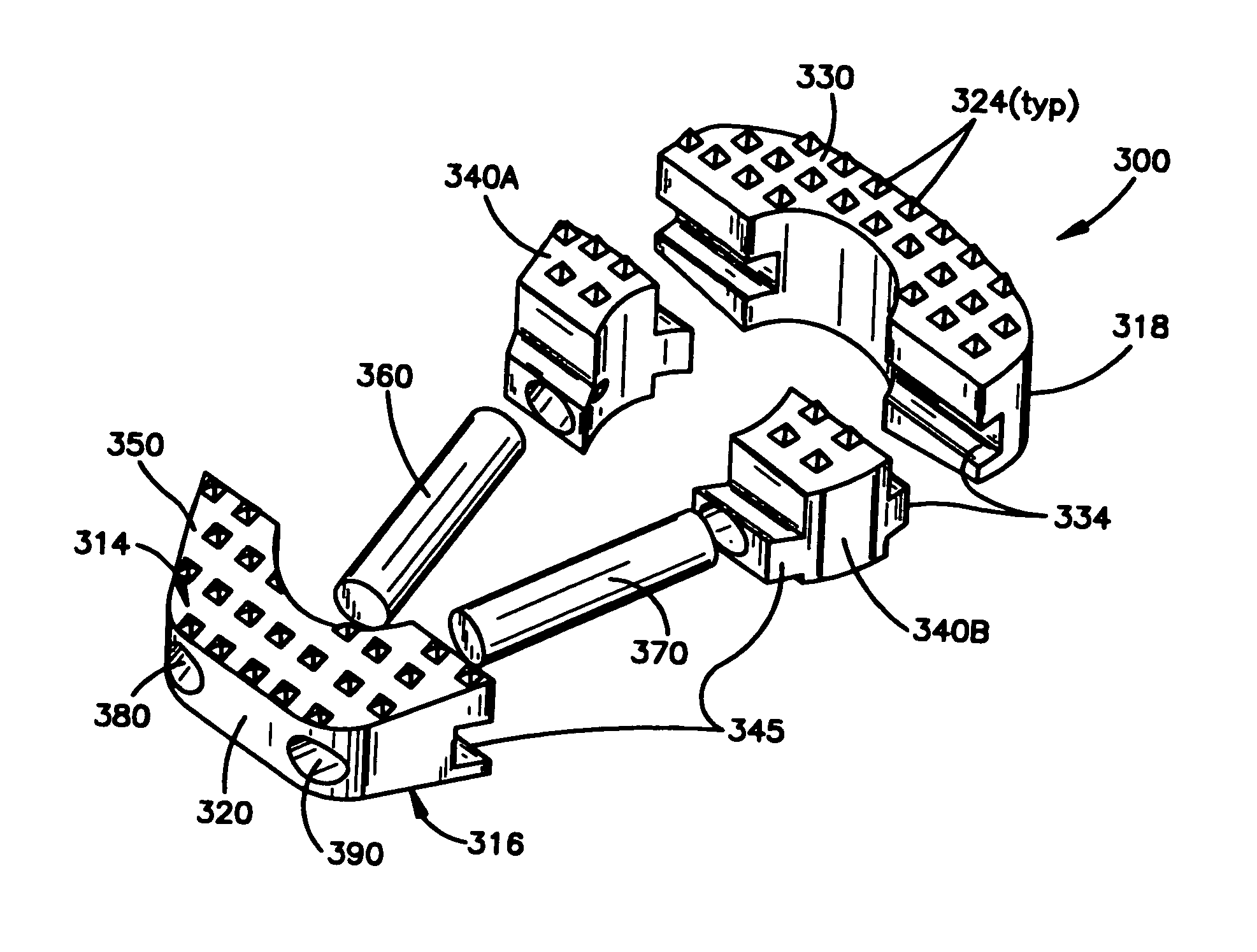
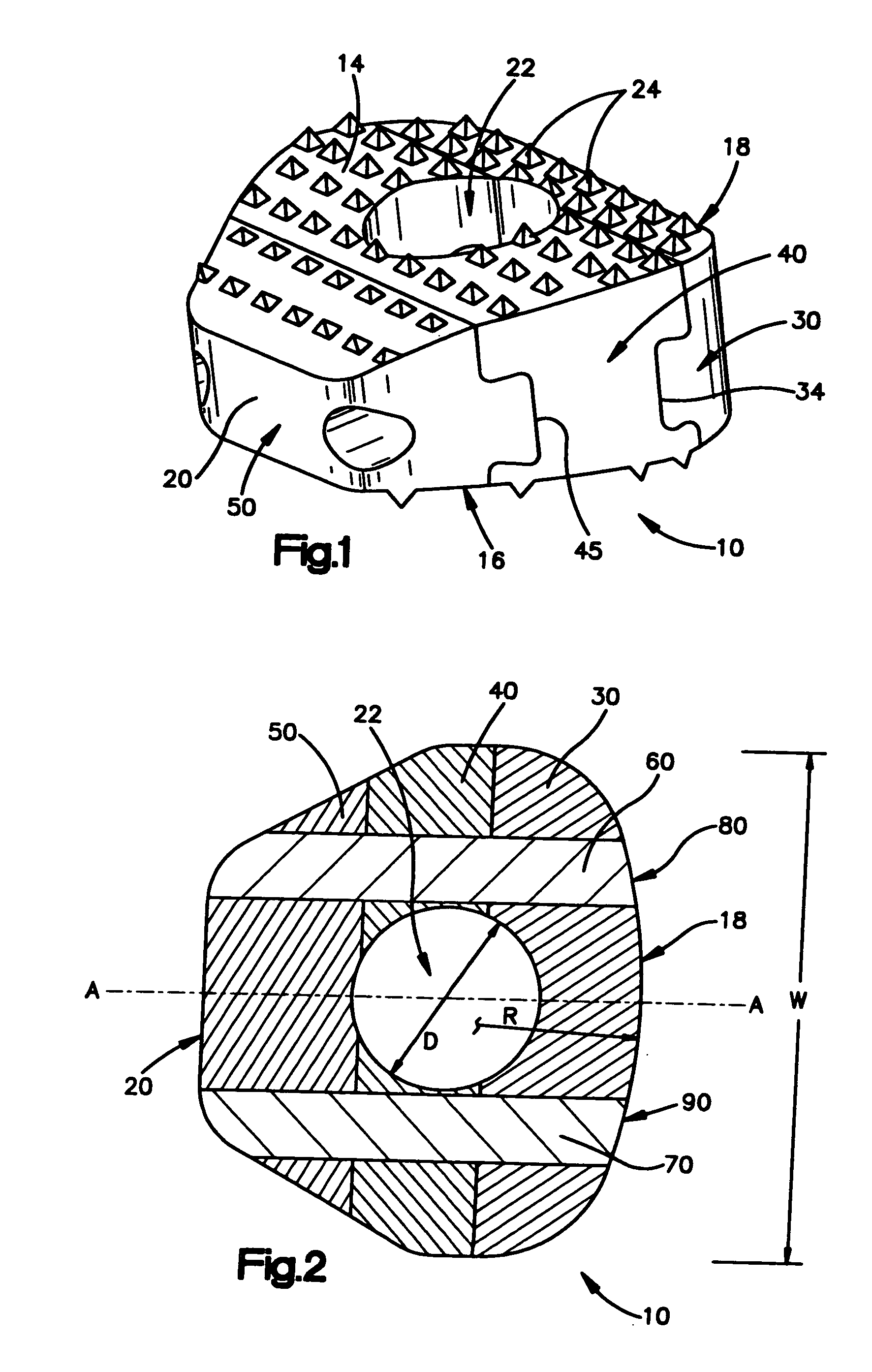
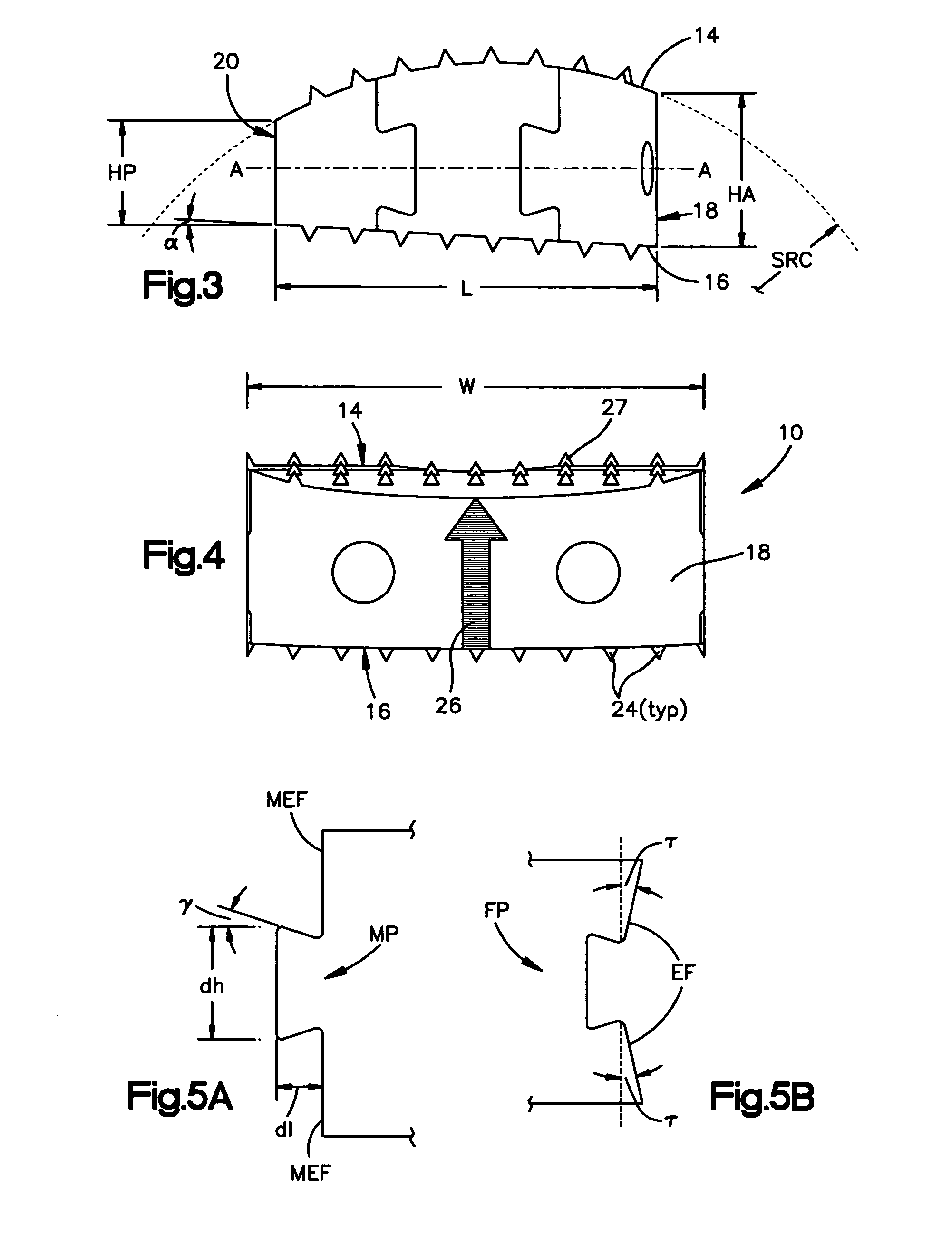
[0061]FIGS. 1-4 show a first embodiment of an intervertebral cortical allograft implant 10 according to the present invention. Implant 10 preferably is shaped to conform in size and shape with at least a portion of the end plates of the vertebrae between which implant 10 is to be inserted. The outer periphery of implant 10 may be sized and shaped to match the outer periphery of the end plates of the vertebrae between which the implant 10 is to be used. Alternatively the outer periphery of the implant 10 may be sized and shaped to match only a portion of the outer periphery of the end plates of the vertebrae, or it may have an outer periphery that may not match the peripheral shape of the end plates of the vertebrae at any location.

[0062] Implant 10 generally comprises a superior surface 14, an inferior surface 16, an anterior face 18, a posterior face 20 and an opening 22. The implant 10 may be substantially symmetrical about a central axis “A-A” which connects and bisects the ante...


PUM


Abstract

An allogenic implant for use in intervertebral fusion is formed from one or more two pieces. The pieces are made from bone, and are joined together to form an implant having sufficient strength and stability to maintain a desired distance between first and second vertebrae in a spinal fusion procedure. The implant pieces may be formed of cortical bone and connected by dovetail joints, and at least one cortical bone pin may be provided to lock the pieces together and to add strength to the implant. Teeth are formed on the vertebra engaging surfaces of the implant prevent short-term slippage of the implant.

Description

FIELD OF THE INVENTION [0001] The present invention is directed to an allogenic implant and, more particularly, to an allogenic intervertebral implant for the fusion of vertebrae. BACKGROUND OF THE INVENTION [0002] A number of medical conditions, such as compression of spinal cord nerve roots, degenerative disc disease, and trauma can cause severe back pain. Intervertebral fusion is a surgical method of alleviating back pain. In intervertebral fusion, two adjacent vertebral bodies are fused together by removing the affected intervertebral disc and inserting an implant that would allow for bone to grow between the two vertebral bodies to bridge the gap left by the removed disc. [0003] A number of different implants and implant materials have been used for fusion with varying success. Current implants for intervertebral fusion include metallic cages, radiolucent implants and allografts. Metallic cages suffer from the disadvantage of requiring drilling and tapping of the vertebral endp...

Claims


Application Information

Patent Timeline
IPC IPC(8): A61B17/88A61B17/92A61F2/00A61F2/28A61F2/30A61F2/44A61F2/46
CPCA61F2/28A61F2310/00359A61F2/44A61F2/4455A61F2/4611A61F2002/2835A61F2002/30057A61F2002/30266A61F2002/30383A61F2002/30387A61F2002/30492A61F2002/30507A61F2002/30571A61F2002/30604A61F2002/30617A61F2002/30782A61F2002/30795A61F2002/3082A61F2002/30843A61F2002/30904A61F2002/4622A61F2002/4628A61F2002/4629A61F2220/0025A61F2230/0082A61F2250/0097A61F2/3094A61F2/46A61B17/92
Inventor RANDALL, BRANDON L.GOODWIN, ROGER D.MESSERLI, DOMINIQUEMYER, JACQUELINEDELURIO, ROBERT J.BOYER, MICHAEL L. IIANGELUCCI, CHRISTOPHER M.
Owner SYNTHES USA
Why Eureka
Try Eureka