
Oil level gauge

Inactive Publication Date: 2005-11-03
PIOLAX CO LTD
View PDF11 Cites 7 Cited by
  • Summary
  • Abstract
  • Description
  • Claims
  • Application Information

AI Technical Summary

Benefits of technology

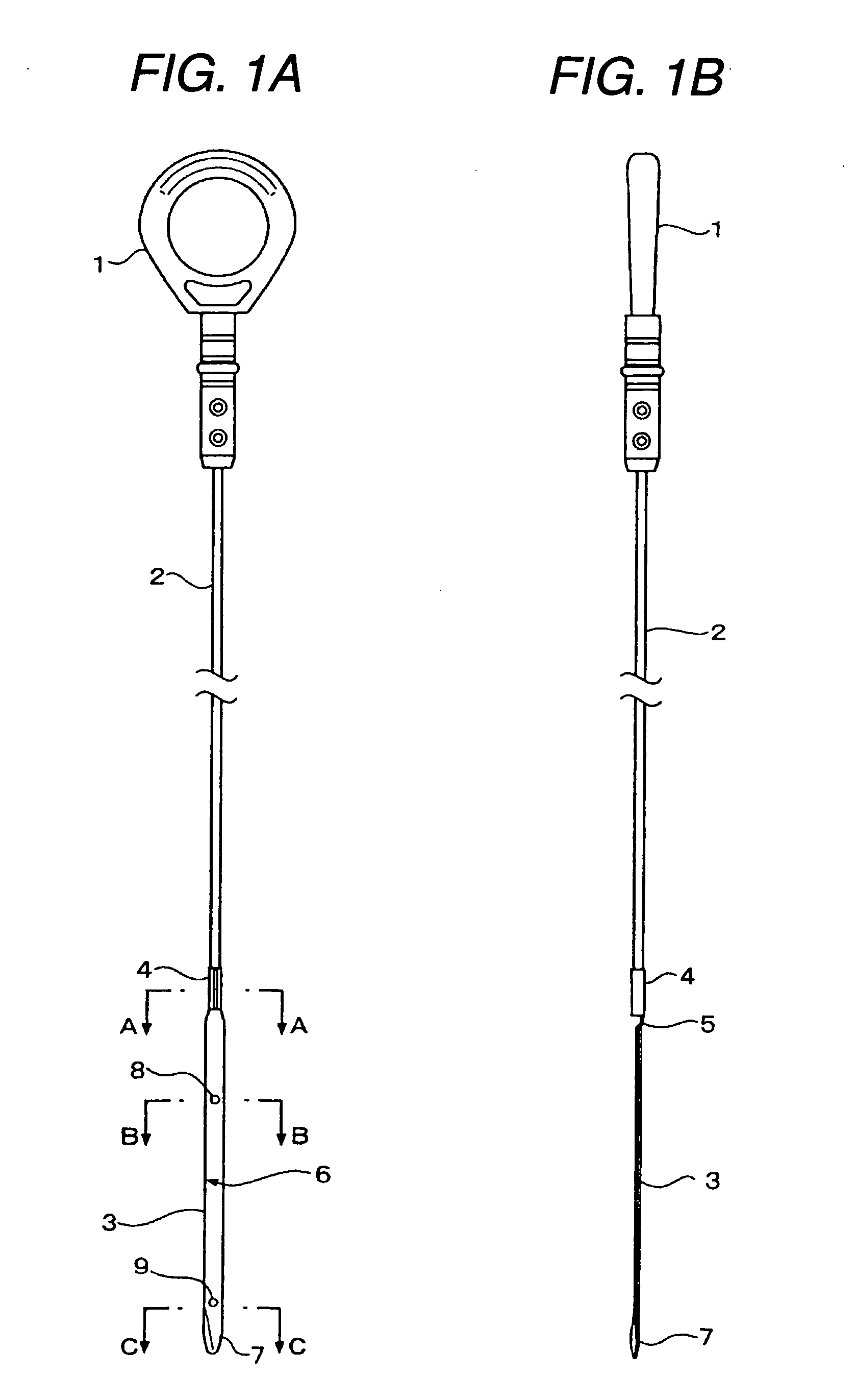
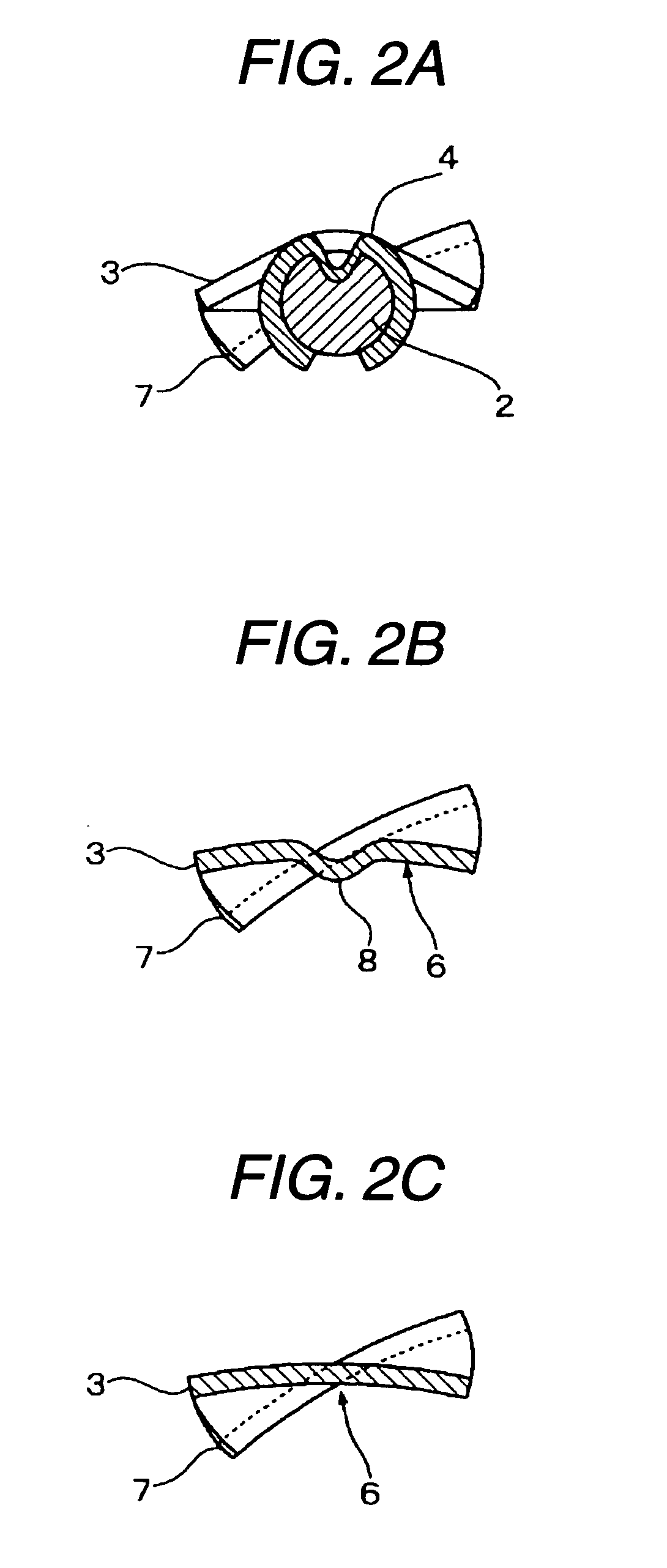
[0008] According to this structure, the measuring section has the curved shape in the direction perpendicular to the longitudinal direction of the measuring section. Therefore, even when the oil level gauge is pulled out of a bent guide pipe in order to measure an engine oil amount, the engine oil adhered to the measuring section is hardly rubbed. As a result, an original oil-level position does not become obscure. Therefore, the amount of engine oil can be checked correctly and precisely, unlike the prior art.
[0010] If the measuring section is curved over the entire length, the rigidity of the measuring section is likely to increase to reduce flexibility. However, according to the structure described above, except for the range indicating an appropriate amount of engine oil, the measuring section has a planar shape, so that flexibility can be enhanced with rigidity suppressed.
[0014] According to this structure, the front end of the measuring section is continuously twisted. Therefore, when the oil level gauge is inserted into the guide pipe, the twisted portion comes into sliding contact with the inner circumferential surface of the guide pipe while a contact point therebetween change continuously. Therefore, the oil level gauge can be smoothly inserted into the guide pipe.
[0016] Since the measuring section is curved in the direction perpendicular to the longitudinal direction, warpage may occur in the longitudinal direction due to a residual stress. However, according to the structure described above, since the both side edges of the measuring section are bent reversely to the curved direction, the warpage is effectively prevented from occurring. Therefore, the amount of engine oil can be checked correctly and precisely.
[0017] According to one embodiment of the present invention, an oil level gauge includes a handle section, a shank section, and a measuring section. The measuring section has a curved shape in a direction perpendicular to a longitudinal direction of the measuring section. Therefore, even when the oil level gauge is pulled out of a bent pipe guide, the engine oil adhered to the measuring section is prevented from being easily rubbed. As a result, an oil-level position of the engine oil can be measured correctly at all times.

Problems solved by technology

Therefore, when the amount of engine oil is measured, an original oil-level position becomes obscure, so that the amount of engine oil cannot be checked correctly and precisely.

Method used


Image

  • Oil level gauge
  • Oil level gauge
  • Oil level gauge

Examples


Embodiment Construction

[0023] Hereinafter, an embodiment of the invention will be described in detail. Similarly to JP-A-Hei. 8-247822, an oil level gauge according to this embodiment also includes three parts, i.e., a handle section 1 made of a synthetic resin, a shank section 2 made of steel wire, and a measuring section 3 made of stainless steel, as shown in FIG. 1. The oil level gauge is used for measuring and checking an amount of engine oil of a car engine and an oxidation state of the engine oil. Specifically, the shank section 2 is formed in a round-rod shape so that it has no directivity when the shank section 2 is inserted into a guide pipe. The shank section 2 and the measuring section 3 are coupled by caulking. Further, the handle section 1 and the shank section 2 are coupled by caulking.

[0024] In addition to the configuration described above, this embodiment has the following features as shown in FIGS. 2 and 3. A C-shaped holding piece 4 for holding a front end of the shank section 2 is inte...


PUM


Abstract

An oil level gauge includes a handle section, a shank section, and a measuring section. The measuring section includes an upper limit mark and a lower limit mark in an up and down direction. The measuring section has a curved shape in a direction perpendicular to a longitudinal direction of the measuring section.

Description

BACKGROUND OF THE INVENTION [0001] 1. Field of the Invention [0002] The present invention relates to an oil level gauge, which is used for measuring and checking an amount of engine oil of a car engine and an oxidation state of the engine oil. [0003] 2. Description of the Related Art [0004] JP-A-Hei. 8-247822 discloses an oil level gauge, which is not shown specifically, including three parts, that is, a handle section, a shank section, and a measuring section. In particular, the measuring section having an elongated flat-plate shape is provided with an oil-level upper limit mark and an oil-level lower limit mark, which indicate an appropriate range of an engine oil amount, in the up and down direction thereof. [0005] Generally, the oil level gauge is inserted into a guide pipe communicating with an oil pan of a cylinder block so that only the measuring section of the oil level gauge is immersed in the engine oil within the oil pan. At the time of measuring and checking, the oil lev...

Claims


Application Information

Patent Timeline
IPC IPC(8): G01F23/04
CPCG01F23/04F21V29/15F21V29/89F21V29/507F21V15/013F21V23/023F21W2131/101
Inventor OYAMA, KENJIOOTSUBO, SEIJI
Owner PIOLAX CO LTD
Learn More