Inertia drive device, unit having the device and method for moving the device

a drive device and inertia technology, applied in the direction of machines/engines, carpet cleaners, machines, etc., can solve the problem that the drive cannot overcome static friction, and achieve the effect of increasing the mechanical effect of the floor

Inactive Publication Date: 2005-11-03
BSH BOSCH & SIEMENS HAUSGERAETE GMBH
View PDF3 Cites 4 Cited by
  • Summary
  • Abstract
  • Description
  • Claims
  • Application Information

AI Technical Summary

Benefits of technology

[0030] It can further be provided that as it operates, the wiping surface moves in an oscillating manner relative to the remaining device, for example swings or circles relative to a base of the device in one or even in two horizontal or vertical directions. Thus the mechanical effect on the floor can be increased, without the same path having to be covered repeatedly.
[0031] This can be the case in relation to the above-mentioned possibilities of smaller retrograde steps made by the inertia drive during the movement according to the invention. Mechanical reinforcement of the wiping effect can be achieved in such a way that the static friction is overcome for a certain phase during the movement actually striven for both in rearwards or laterally directed movements. In the process, quasi-oscillating (and not necessarily continuous) movements can be attained.

Problems solved by technology

The drive does not overcome static friction holding the base on the surface in another part of the movements of the inertial mass.

Method used


Image

  • Inertia drive device, unit having the device and method for moving the device
  • Inertia drive device, unit having the device and method for moving the device
  • Inertia drive device, unit having the device and method for moving the device

Examples


Embodiment Construction

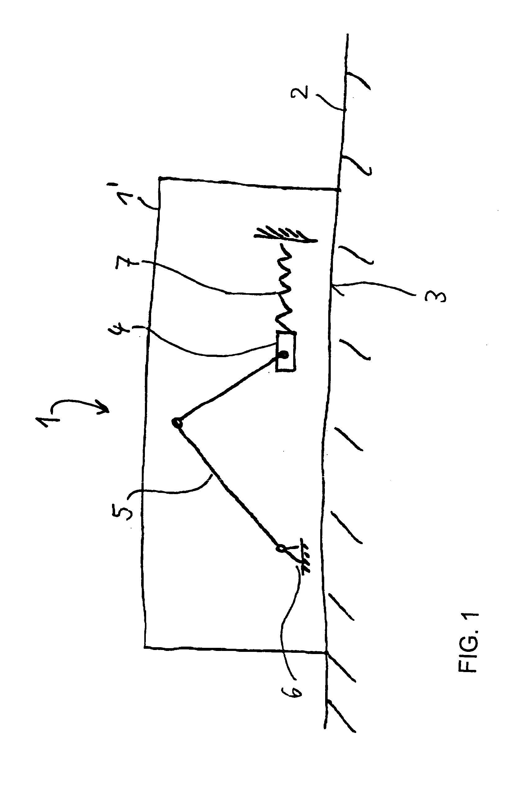
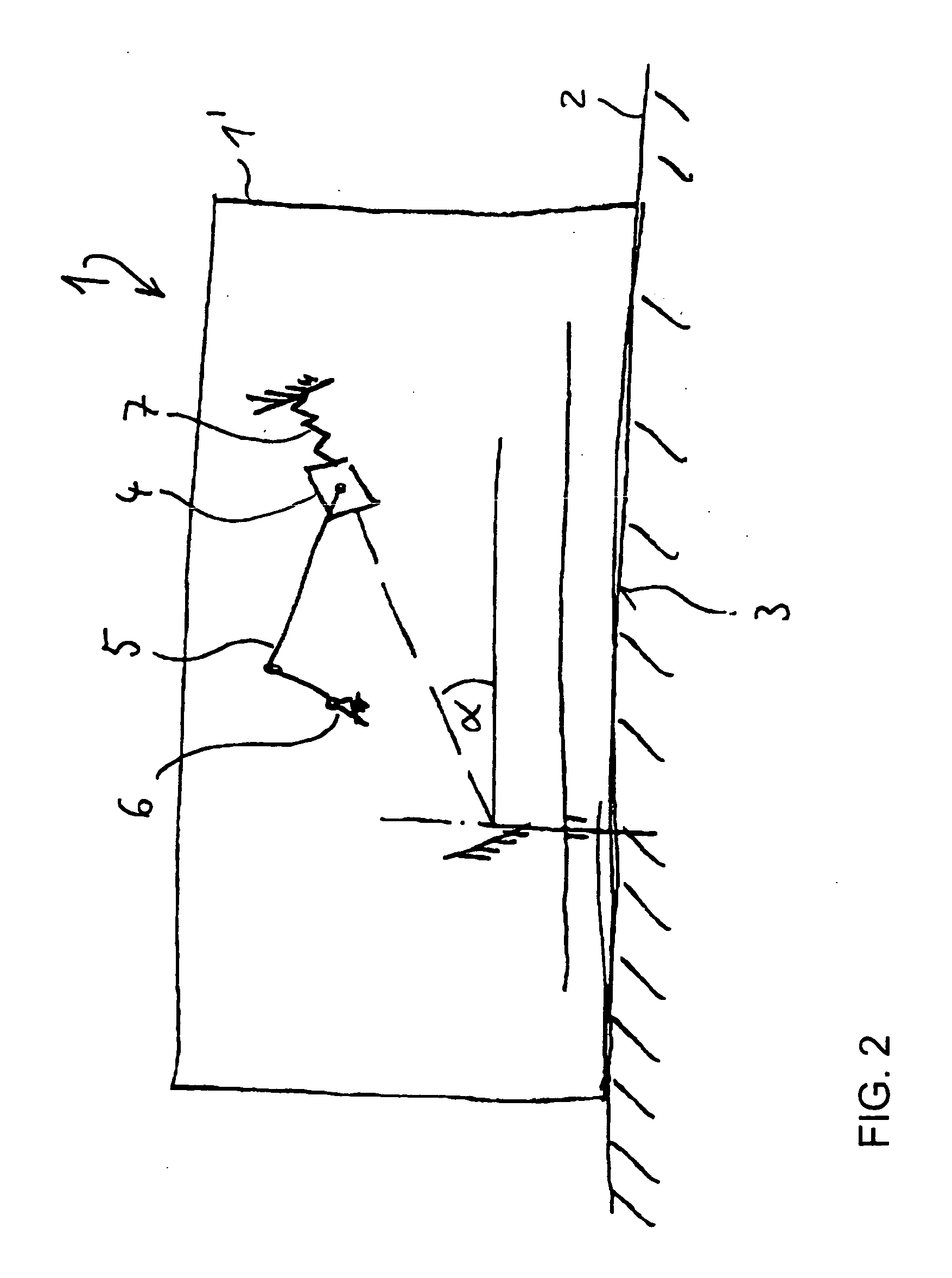
[0065] Referring now to the figures of the drawings in detail and first, particularly, to FIG. 1 thereof, there is seen a highly diagrammatic illustration of the principle of an inertia, flywheel, centrifugal or gyrating drive according to the invention. In FIG. 1 a wiping device for moist wiping and thus cleaning of floors in a household or in other inside rooms is designated with reference numeral 1. The wiping device 1 is illustrated in FIG. 1 as having a base 1′ in the from of a simple box. The wiping device 1 lies on a floor 2 and faces the latter with a wiping surface 3.

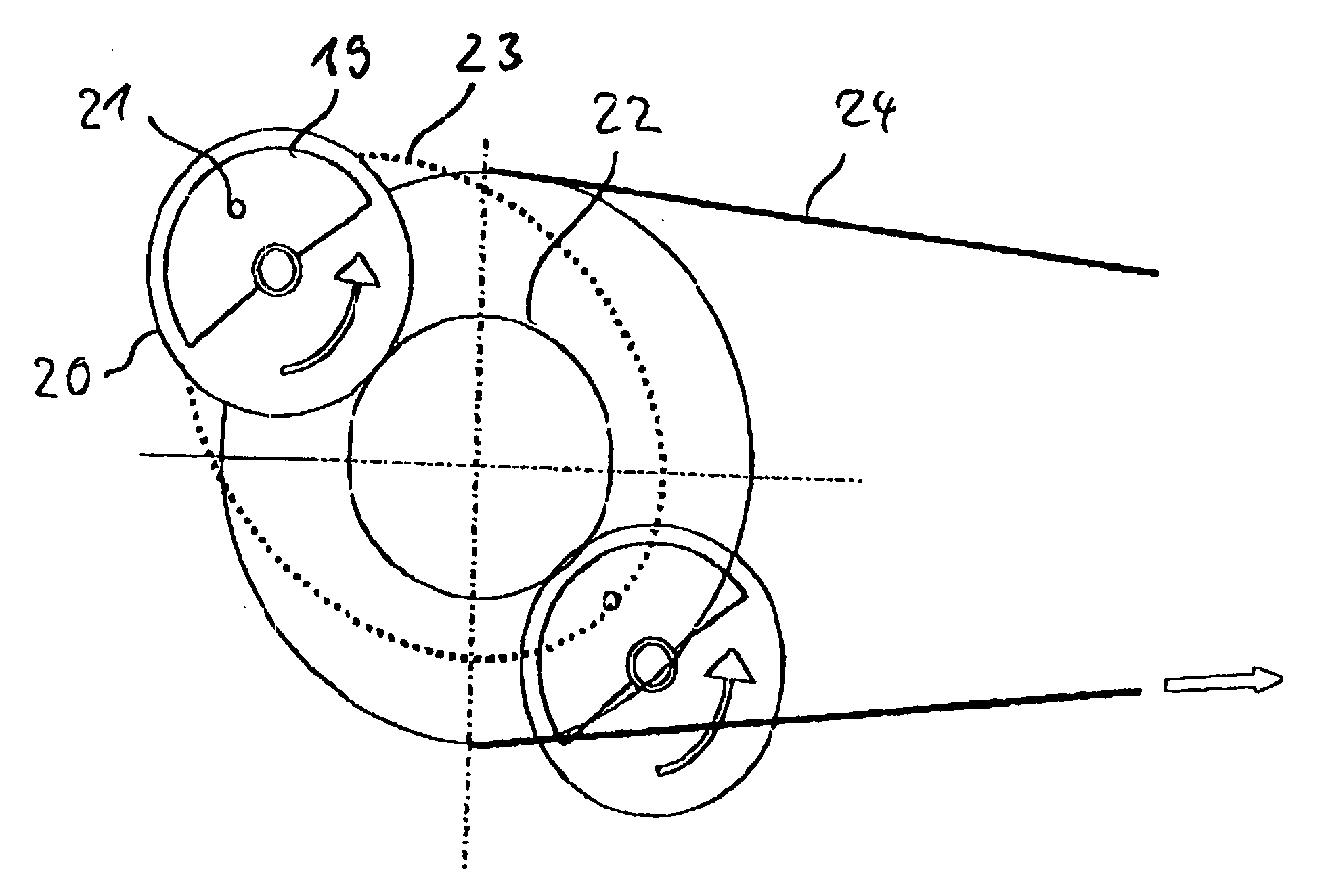
[0066] An inertia or centrifugal mass 4, which is provided in the wiping device 1 and is only symbolically illustrated in this case, is disposed in such a way as to be movable and horizontal in a manner that is not illustrated in greater detail. In the present case, as is likewise only symbolically illustrated, the inertia or gyrating mass 4 is powered by a lever system 5 from a drive motor 6 and against the f...


PUM


Abstract

A motor-driven mobile device has an inertial drive which overcomes static friction between the device and a surface by inertial mass movements and resulting inertial forces in specific phases and recycling the inertial mass movements in other phases, without the static friction being overcome. A unit for regenerating the mobile device and a method for moving the device over a surface, are also provided.

Description

CROSS-REFERENCE TO RELATED APPLICATIONS [0001] This is a continuing application, under 35 U.S.C. § 120, of copending International Application No. PCT / EP2003 / 012960, filed Nov. 19, 2003, which designated the United States; this application also claims the priority, under 35 U.S.C. § 119, of German Patent Application 102 56 091.9, filed Dec. 2, 2002; the prior applications are herewith incorporated by reference in their entirety.BACKGROUND OF THE INVENTION [0002] Field of the Invention [0003] The present invention relates to a motor-driven inertia drive device, which can be moved over a surface through the use of a drive. The invention also relates to a unit having the device and a method for moving the device. SUMMARY OF THE INVENTION [0004] It is accordingly an object of the invention to provide an inertia drive device, a unit having the device and a method for moving the device, which overcome the disadvantages of the heretofore-known devices and methods of this general type. [000...

Claims


Application Information

Patent Timeline
Patent Type & Authority Applications(United States)
IPC IPC(8): A47L13/256A47L13/48A47L13/60F03G3/08
CPCA47L13/256A47L13/48Y10T74/18536F03G3/08A47L13/60F03G7/10
Inventor DAMRATH, JOACHIMSPIELMANNLEITNER, MARKUSWETZL, GERHARD
Owner BSH BOSCH & SIEMENS HAUSGERAETE GMBH
Why Eureka
Try Eureka