Drop tube segments adapted for use with a liquid reservoir

Active Publication Date: 2005-11-03
OPW FUELING COMPONENTS LLC
View PDF52 Cites 25 Cited by
  • Summary
  • Abstract
  • Description
  • Claims
  • Application Information

AI Technical Summary

Benefits of technology

[0007] Accordingly, it is an aspect of the present invention to obviate problems and shortcomings of conventional drop tube assemblies. More particularly, it is an aspect of the present invention to provide a drop tube segment with a fastening section that provides a fluid tight seal to inhibit, such as prevent, fluid l

Problems solved by technology

A fluid tight seal may reduce or prevent fluid, such as vapor, from being released from the ullage area of the reservoir to the interior of the drop tube that might act as a chimney to vent the fluid to the surrounding atmosphere and potentially create an en

Method used


Image

  • Drop tube segments adapted for use with a liquid reservoir
  • Drop tube segments adapted for use with a liquid reservoir
  • Drop tube segments adapted for use with a liquid reservoir

Examples


Embodiment Construction

[0035] The various exemplary embodiments of the invention may be used to provide a valve system for a wide variety of applications. For example, the various exemplary embodiments of the invention may be used to provide overfill valve systems for use in a liquid reservoir, such as a liquid storage tank. In one particular example, features of the exemplary embodiments herein may be used in addition, or in place of, features disclosed in U.S. Pat. No. 4,986,320, which is herein incorporated entirely by reference. U.S. Pat. No. 4,986,320 is referred to throughout this application as “the referenced patent”.

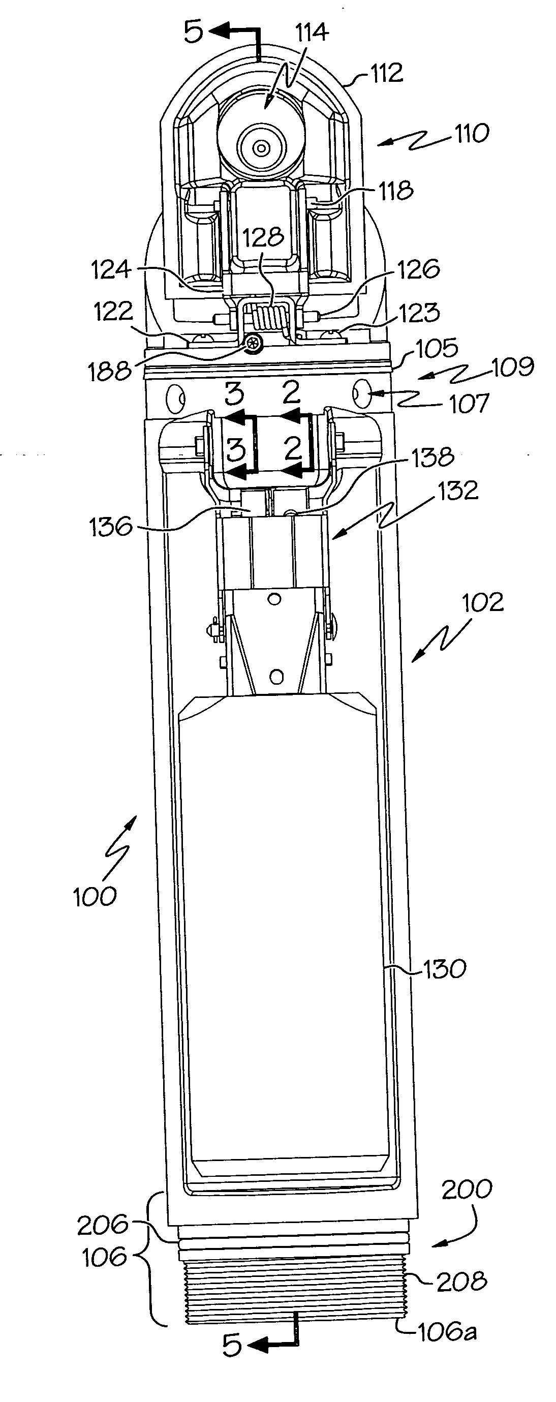
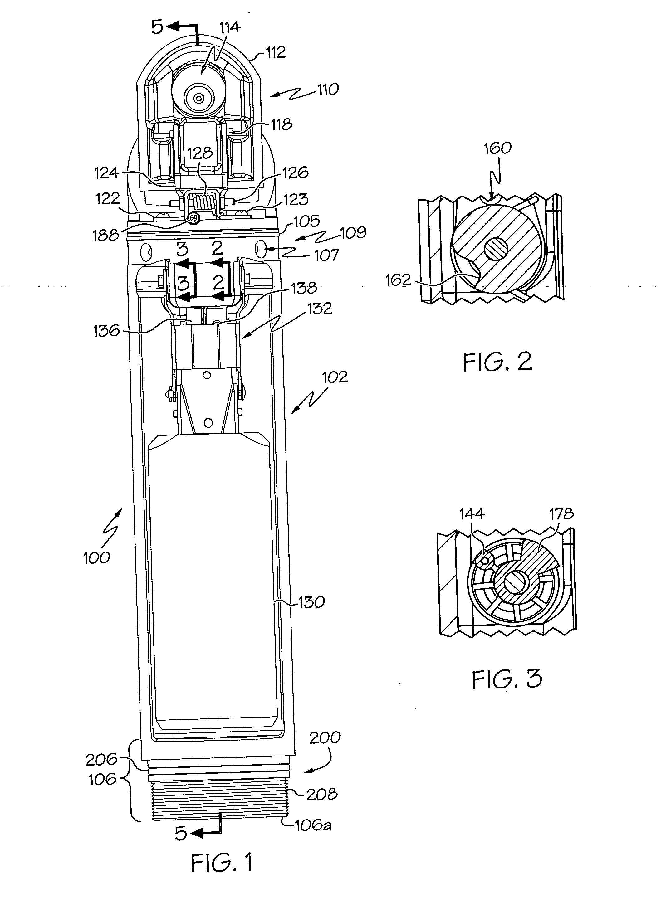
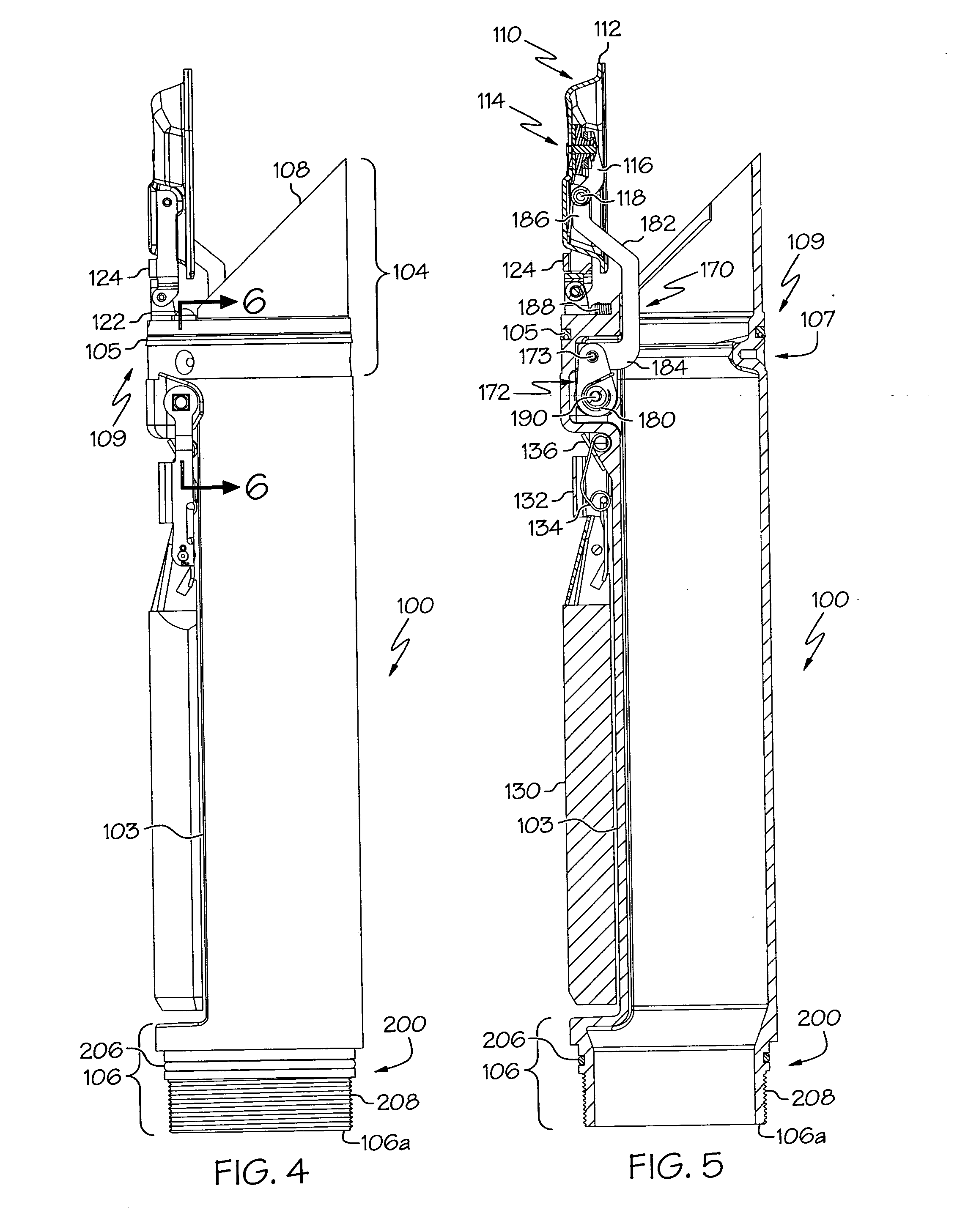
[0036] Attention will now be directed to various exemplary embodiments of the invention. Concepts of exemplary embodiments are illustrated in the accompanying drawings, wherein like numerals indicate the same elements throughout the views. With reference to FIGS. 1, 4 and 5, a drop tube segment 100 in accordance with one embodiment of the present invention is disclosed. The drop tube...


PUM

PropertyMeasurementUnit
Dimensionaaaaaaaaaa
Levelaaaaaaaaaa
Resilienceaaaaaaaaaa

Abstract

A drop tube segment includes a conduit with a first end portion and a second end portion. The drop tube segment further comprises a valve assembly with a valve member associated with the first end portion, a float, and a linkage device pivotally connected with respect to the valve member. The linkage device is adapted for communication with the float such that the float may facilitate in adjusting the position of the valve member with respect to the first end portion of the conduit in response to a liquid level in a liquid reservoir. The drop tube segment further includes a fastening section located at the second end portion of the conduit for fluid tight fastening with an end portion of another drop tube segment. The fastening section comprises a sealing surface and a threaded portion adapted for threaded engagement with a threaded portion of another drop tube segment. The drop tube segment still further includes a sealing member that engages the sealing surface of the fastening section and is adapted to engage a sealing surface of another drop tube segment.

Description

TECHNICAL FIELD [0001] The present invention relates generally to drop tube segments, and more particularly to drop tube segments including a fastening section for use with a liquid reservoir. BACKGROUND OF THE INVENTION [0002] Our increasingly mobile and mechanized society uses a variety of different fuels (e.g., gasoline, diesel fuel, ethanol, etc.) as energy. Liquid fuels are generally stored in liquid reservoirs such as underground storage tanks, above ground tanks, or any of a variety of different containers. Typically, liquid fuel reservoirs have inlets and outlets through which fuel can be added to and / or removed from the reservoir. These inlets and outlets may typically consist of a riser pipe extending from the reservoir. Internal to the riser pipe is a drop tube that typically includes an overfill valve adapted to respond once a predetermined level is reached in the liquid reservoir. To simplify manufacture and assembly, it is also known to provided the drop tube in a plur...

Claims


Application Information

Patent Timeline
IPC IPC(8): B65D90/26B65D90/00B67D7/36B67D7/78F16L15/04
CPCF16L15/008F16L15/001Y10T137/7439B67D7/365F16K15/141F16K27/0209B65D90/26F16K31/18
Inventor PENDLETON, DAVID R.KESTERMAN, JAMES E.KANE, KRISTOPHER A.
Owner OPW FUELING COMPONENTS LLC
Why Eureka
Try Eureka