Variable orifice bypass plunger

a plunger and variable orifice technology, applied in the direction of fluid removal, borehole/well accessories, construction, etc., can solve the problems of reducing the lifting efficiency geometrically, affecting the production efficiency of wells, and gas phase cannot support liquid in droplet form or slug form, so as to achieve efficient lift-in, improve the production efficiency of wells, and improve the effect of liquid wells

Inactive Publication Date: 2005-11-03
PCS FERGUSON
View PDF29 Cites 61 Cited by
  • Summary
  • Abstract
  • Description
  • Claims
  • Application Information

AI Technical Summary

Benefits of technology

[0031] The variable orifice by-pass plunger (VOBP) of the present invention allows more than one orifice setting in the by-pass valve. The VOBP contains a variable orifice valve (VOV) that has a variable orifice that can easily be set to more than one position. When released from the auto catcher, the orifice will function to allow liquid to pass through the plunger lower valve section and up through the plunger top section during its return trip to the well bottom. The well control system will release it to fall back into the well when conditions are satisfied. Depending on the high liquid well parameters, the VOV can be set to op

Problems solved by technology

As the flow rate and pressures decline in a well, lifting efficiency declines geometrically.
First, as liquid comes in contact with the wall of the production string of tubing, friction occurs.
Secondly, as the flow velocity continues to slow, the gas phase can no longer support liquid in either slug form or droplet form.
Because of the small tubing diameters, a relatively small amount of liquid may cause a well to load-up, or a relatively small amount of paraffin may plug the tubing.
In addition, friction between the gas and tubing acts to slow the expansion of the gas.
In certain high liquid wells, fluid build up hampers the plunger's decent during the return trip

Method used


Image

  • Variable orifice bypass plunger
  • Variable orifice bypass plunger
  • Variable orifice bypass plunger

Examples


Embodiment Construction

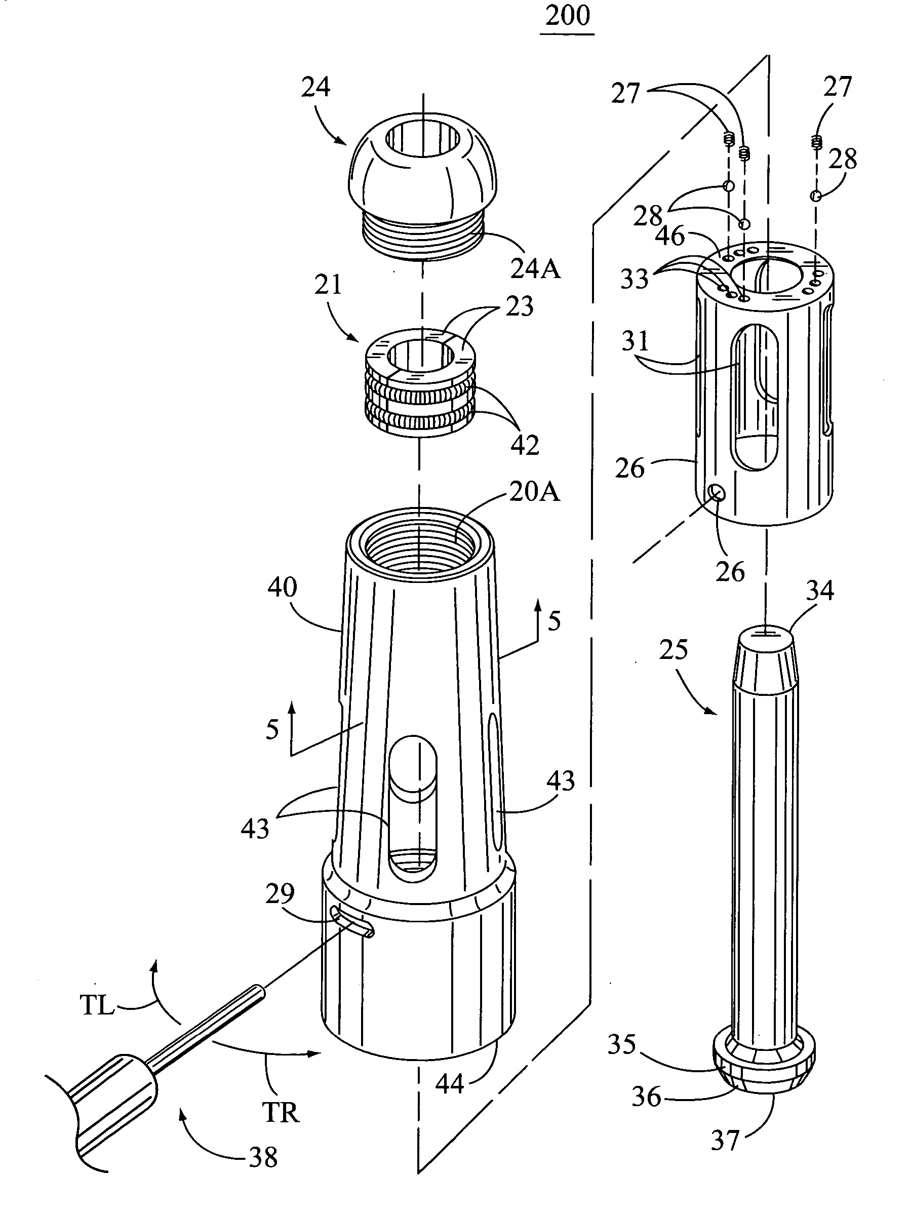
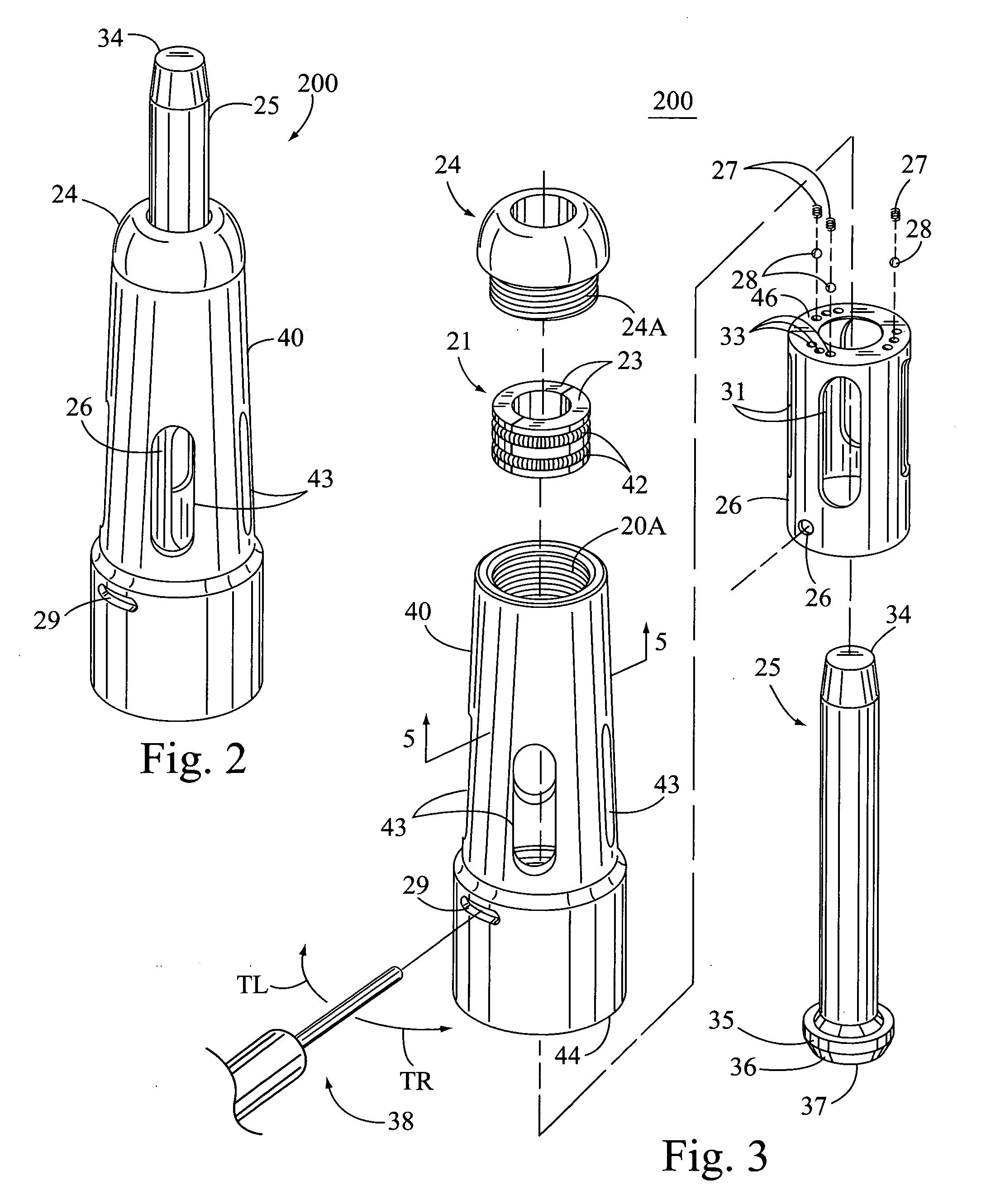
[0045] Referring now to the drawings, the present invention provides a variable orifice by-pass plunger (VOBP) apparatus (see item 1000 of FIG. 11) that will increase well production levels in a high liquid well. The VOBP contains a lower section variable orifice valve (VOV) 200 (see FIGS. 2, 3, 4, 10) that can be easily preset to several different levels, the preferred embodiment having three set levels. The VOBP is designed to be set to an optimized by-pass orifice opening to efficiently force fall through liquid inside the tubing to the well-hole bottom. This optimization of the orifice setting will optimize return-speed through liquid and thus optimize well production. VOV 200 has an internal by-pass shut off mechanism, which will close the by-pass feature once the plunger reaches the well bottom. A shut off condition is required in order to provide for proper plunger return lift to the well top. Concurrently, the plunger by-pass valve will be re-opened to its preset condition o...


PUM


Abstract

An improved plunger mechanism apparatus has a manually adjustable bypass valve to increase well flow production levels in high liquid wells. The plunger's descent rate can be fine tuned in the field by adjusting the orifice opening so that liquid can optimally flow through the plunger core during descent. Efficiency of well flow is increased by the addition of a variable bypass orifice, which can be preset in numerous positions to vary the amount of liquid bypass allowed depending on the well loading parameters. The plunger mechanism of the present invention allows numerous bypass set positions, which can be tuned at a well site and later changed as a function of future well loading parametric changes.

Description

CROSS REFERENCE APPLICATIONS [0001] This application is a non-provisional application claiming the benefits of provisional application No. 60 / 563,711 filed Apr. 20, 2004.FIELD OF THE INVENTION [0002] The present invention relates to an improved plunger lift apparatus for the lifting of formation liquids in a hydrocarbon well. More specifically the improved plunger consists of a variable orifice in a bypass plunger apparatus that operates to allow a variation in plunger bypass capabilities as a function of well parameters. BACKGROUND OF THE INVENTION [0003] A plunger lift is an apparatus that is used to increase the productivity of oil and gas wells. In the early stages of a well's life, liquid loading is usually not a problem. When rates are high, the well liquids are carried out of the well tubing by the high velocity gas. As the well declines, a critical velocity is reached below which the heavier liquids do not make it to the surface and start to fall back to the bottom exerting ...

Claims


Application Information

Patent Timeline
IPC IPC(8): E21B33/03E21B43/12
CPCE21B43/127E21B43/121
Inventor VICTOR, BRUCE M.
Owner PCS FERGUSON
Why Eureka
Try Eureka