Integrated buoyancy joint

a buoyancy joint and integrated technology, applied in the direction of special purpose vessels, seals/packings, borehole/well accessories, etc., can solve the problems of prohibitively expensive stiffening, difficult access, and inconvenient use of conventional offshore oil production methods using a fixed truss type platform, etc., to achieve the effect of improving the buoyancy system, being easy to manufacture, transport and install

Active Publication Date: 2005-11-03
ALBANY ENGINEERED COMPOSITES
View PDF82 Cites 33 Cited by
  • Summary
  • Abstract
  • Description
  • Claims
  • Application Information

AI Technical Summary

Benefits of technology

[0023] It has been recognized that it would be advantageous to develop an improved buoyancy system for offshore oil platforms. It has been recognized that it would be advantageous to develop a buoyancy system that is inexpensi...

Problems solved by technology

Conventional offshore oil production methods using a fixed truss type platform are not suitable for these water depths.
Stiffening them to avoid excessive and damaging dynamic responses to wave forces is prohibitively expensive.
Flexible and SCR type production risers require the wellhead control valves to be placed on the seabed where access is difficult and maintenance is expensive.
TTR tensioning systems are a technical challenge, especially in very deep water where the required top tensions can be 1,000,000 lbs (1,000 kips) or more.
These types of vessels are only suitable for flexible risers, or other free-standing systems.
As tensions and stroke requirements grow, these active tensioners become prohibitively expensive.
They also require large deck area, and the buoyancy loads have to be carried by the FPS structure.
Even the most recent designs for large buoyancy cans used on Spars are limited in diameter and overall length, and may not be feasible or cost-effective where the net buoyancy requirement is in the range of 3000-4000 kips.
One disadvantage with TTR air cans is that they are normally formed of metal, and thus add considerabl...

Method used


Image

  • Integrated buoyancy joint
  • Integrated buoyancy joint
  • Integrated buoyancy joint

Examples


Embodiment Construction

[0037] Reference will now be made to the exemplary embodiments illustrated in the drawings, and specific language will be used herein to describe the same. It will nevertheless be understood that no limitation of the scope of the invention is thereby intended. Alterations and further modifications of the inventive features illustrated herein, and additional applications of the principles of the inventions as illustrated herein, which would occur to one skilled in the relevant art and having possession of this disclosure, are to be considered within the scope of the invention.

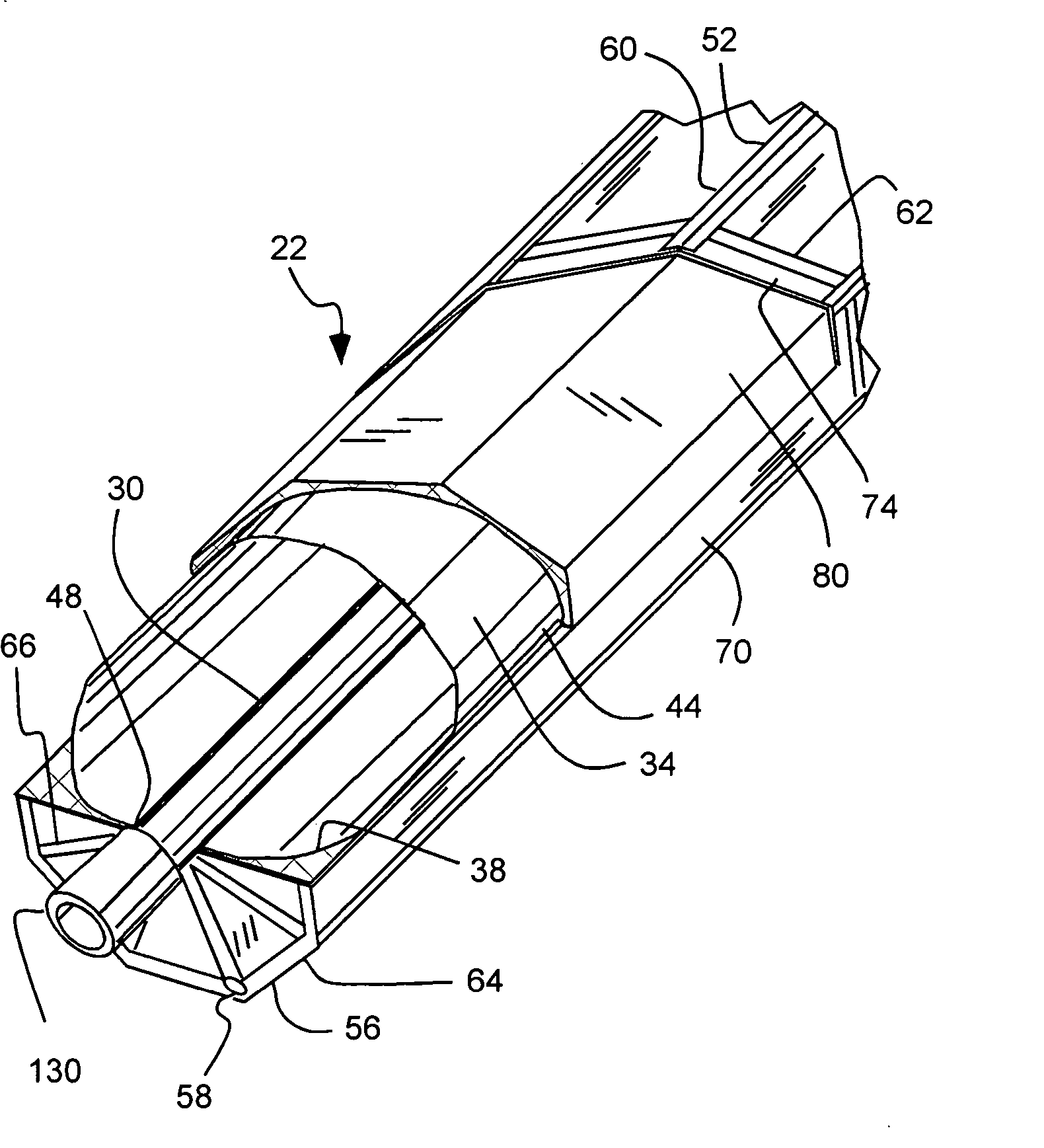
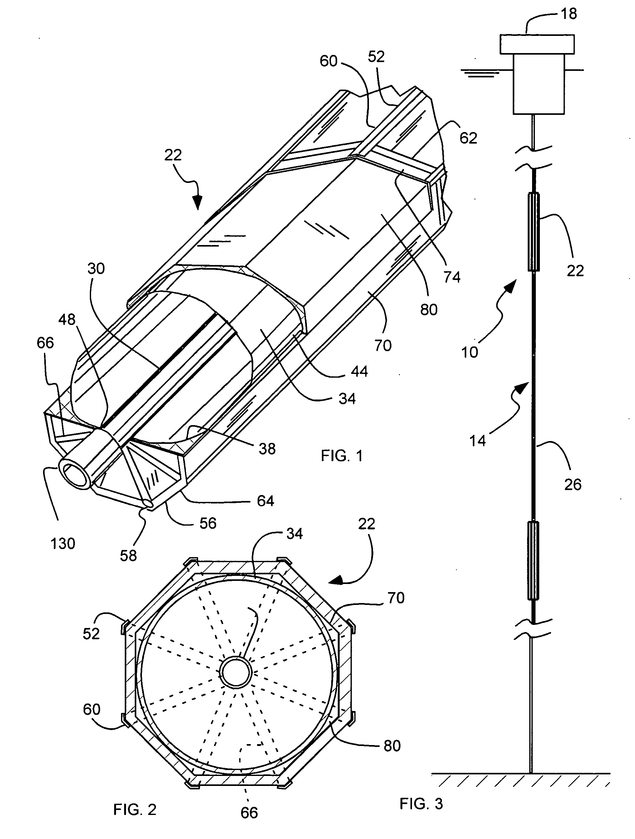
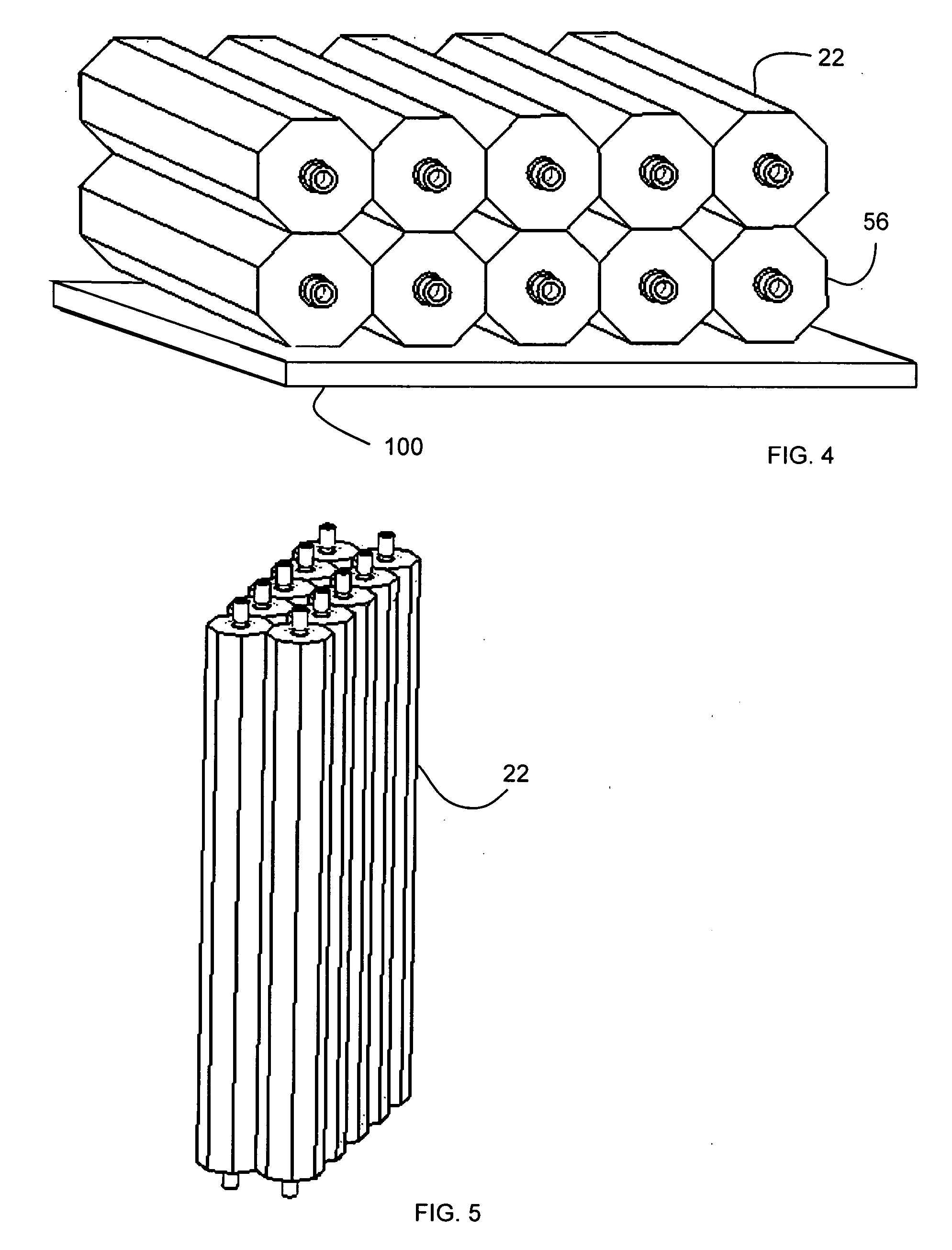
[0038] As illustrated in FIGS. 1-7, a buoyancy system, indicated generally at 10, in accordance with the present invention is shown for providing buoyancy to a riser system 14 extending from an offshore oil platform 18 to wellheads or control modules on the ocean floor. The system 10 can include a plurality of integrated buoyancy joints (IBJ) 22 that can be coupled in series with a plurality of riser sections 2...


PUM


Abstract

A buoyancy system includes a plurality of buoyancy joints distributed along a riser system. Each joint can include a riser pipe, an external frame disposed around a riser and a vessel, and a buoyant cladding disposed between the vessel and the frame.

Description

[0001] Priority is claimed of U.S. Provisional Patent Application Nos. 60 / 568,101, filed May 3, 2004, and 60 / 568,478, filed May 5, 2004.BACKGROUND OF THE INVENTION [0002] 1. Field of the Invention [0003] The present invention relates generally to buoyancy for offshore oil production. [0004] 2. Related Art [0005] As the cost of oil increases and / or the supply of readily accessible oil reserves are depleted, less productive or more distant oil reserves are targeted, and oil producers are pushed to greater extremes to extract oil from less productive oil reserves, or to reach more distant oil reserves. Such distant oil reserves may be located below the oceans, and oil producers have developed offshore drilling platforms in an effort to extend their reach to these oil reserves. In addition, some oil reserves are located farther offshore, and thousands of feet below the surface of the oceans. [0006] For example, vast oil reservoirs have recently been discovered in very deep waters around...

Claims


Application Information

Patent Timeline
IPC IPC(8): E21B17/01
CPCE21B17/012
Inventor JONES, RANDY A.KENNEDY,, DANIEL C. II
Owner ALBANY ENGINEERED COMPOSITES
Why Eureka
Try Eureka