Thereafter, studies conducted pertaining to the use of lifters taught away from lifter implementation, concluding ineffective roll control at high angles of
attack, which is a problem that designers of fighter aircraft were trying to solve.
Use of ailerons, however, invite a number of adverse flight conditions and reduce some aspects of flight performance.
One issue includes the inherit limitation of
aileron functionality.
When attempting to create lift on one wing, excessive downward deployment of the associated
aileron may result in a loss of lift on the associated wing.
Further, deployed ailerons and their associated
actuator and hinges create drag.
Increased drag forces degrade performance and require additional flight components to offset untoward effects.
For example, the drag generated by extension of the
aileron on one wing may result in adverse
yaw moments, where the aircraft
nose is forced in a direction opposite to its intended turn, such that the aircraft's longitudinal axis forms an angle with its intended direction of flight.
While the ailerons may be typically used symmetrically on both sides so these
yaw forces from aileron drag cancel each other out, some inboard ailerons can induce a large
angle of attack (sidewash) on the vertical
tail caused by the flow's rotation around
fuselage and resulting in huge loads on the structure of the entire aft body and very unfavorable yawing moment.
These undesirable effects may or may not be countered with the
rudder, depending how powerful the
rudder is.
Some aircraft, for example, do not have enough
rudder power to counter these conditions.
Various ailerons and rudder control functionality, however, requires large,
complex system configurations, which typically results in greater overall weight, thus further degrading aircraft performance and capabilities, particularly in specific types of aircraft which rely on streamlined, lightweight designs to achieve high speeds or high efficiency and high maneuverability, such as fighter aircraft.
Deflection of spoilers creates air
pressure buildup forward of it, so an increase in pressure on the upper
skin and no change on the lower
skin by definition results in reduction of lift as well as creation of drag, and, if used symmetrically, spoilers have a little profile drag but mainly they destroy a lot of lift.
Spoilers cause large
pressure buildup in front of them and so they destroy lift in that section of the wing.
Net lift on that (left or right) wing is smaller than the opposite side wing, causing that wing to start sinking, which creates roll and turns the
airplane.
The use of spoilers, however, is limited by the available upper surface area, the
relative thickness of the wing, and positional and operational considerations affecting flight control on different wing models.
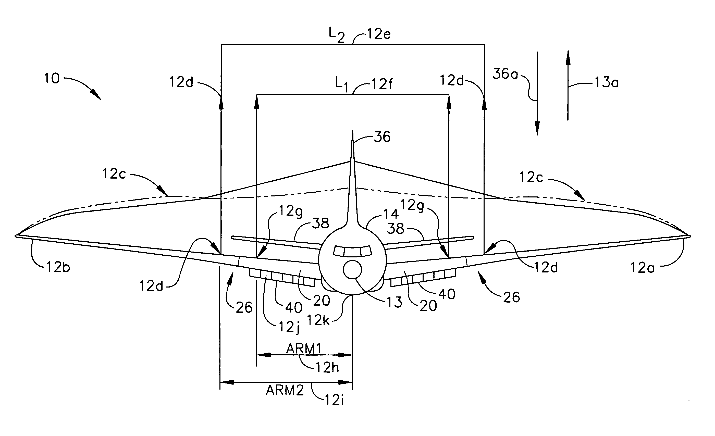
Another flight control issue centers around loading on the wing.
When the
airplane is pulling g's, or accelerating upward at, for example, 2.5×g (9.81 m / sec2), the wings have to sustain the load of approximately 2.5 times the weight of the
airplane, resulting in an undesirable
bending moment.
Despite the use of various flight control devices, certain aircraft such as high-speed, high-efficiency, long-range aircraft are particularly susceptible to flight control issues.
Further, aircraft having relatively thin, long wings tend to suffer aeroelastic loss (
bending moment) during roll maneuvers, including those deploying outboard ailerons (positioned relatively near to the wingtip) or middle ailerons (positioned mid-wing relative to the wingtip and the body of the aircraft).
A thin, hollow wing or wing structure is by nature less stiff than a thick wing design, therefore prone to high tip bending or flexibility.
A flexible aft
swept wing is by definition aeroelastic, so prone to aeroelastic effectiveness loss of any outboard device (aileron or
spoiler).
This aeroelastic phenomenon may make any economically viable commercial airplane design very sluggish in roll maneuvers, and possibly uncertifiable by regulatory agencies such as the FAA.
This may also make military platforms too sluggish and, therefore, unacceptable for performance requirements for certain aircraft having, for example, thin-wing, long-span, high efficiency semi-
delta wings.)
Deployment of outboard ailerons for roll purposes can actually reverse roll effectiveness, thus cannot be used during roll maneuvers.
Middle ailerons lose their effectiveness when deployed at relatively high speeds—Mach 0.9, for example—and at relatively high dynamic pressures.
Inboard ailerons (positioned closer to the body of the aircraft than to the wingtip) provide only about one-third of the required roll control for commercial transports and even less of a fraction for many military mission airplanes, and are thus insufficient as a viable flight control solution.
Theoretically, both middle ailerons and inboard ailerons could be deployed to achieve more roll; however, in practice hinge moments (load on hinge devices) become intolerable and still result in deficient roll control.
Further, the upflow of air on one side of the aircraft and downflow on the other caused by use of the left wing inboard ailerons and right wing inboard ailerons, respectively, produce a circular or
spiral flow around the
fuselage from wing to
tail, inducing an
angle of attack (or sidewash) on the vertical
tail that produces significant yawing moments.
Such yawing moment is untrimmable by a reasonably configured rudder; i.e., a rudder that appropriately conforms to size and weight requirements for a particular model of aircraft.
The
adverse effect of such use of the inboard ailerons is particularly severe on aft wing—canard configurations (aircraft having a horizontal stabilizer in front of the wings, such as some models having twin vertical tail configurations), due to the relative proximity of the vertical tail and the
trailing edge devices.
Further, concurrent use of the middle and inboard ailerons produces huge loads which the structure must sustain, thus necessitating heavier components, increasing costs, and decreasing performance.
Spoilers, however, are also subject to aeroelastic loss, albeit to a lesser degree than ailerons.
Thus, spoilers recover some roll power, but not enough to meet commercial transport requirements; for example, 60 degrees / 4 seconds with one hydraulic
system unoperational.
In certain aircraft embodiments, spoilers located in front of inboard ailerons decrease the effectiveness of inboard ailerons, thus negating the benefit derived from inboard placement of the ailerons.
Because the middle ailerons have little effectiveness, some designs curtail
actual use of the aileron, thus saving on construction costs for the
actuator or other components used as deployment mechanisms.
Another possible configuration, with inboard ailerons and spoilers located in front of the middle ailerons, still fails to produce an acceptable level of roll control.
Yet another configuration consisting of spoilers located in front of the outboard ailerons fail to produce the desired drag due to the
aeroelasticity of the wing at that location.
Further, many configurations do not provide enough configurable space at the outer wing to accommodate spoilers.


