Methods for processing a received signal in a software defined radio (SDR) system, a transceiver for an SDR system and a receiver for an SDR system

a software defined radio and received signal technology, applied in the direction of digital transmission, modulated carrier system, electrical apparatus, etc., can solve the problems of serious finite word length effect, narrow usable passband of cic filter, and use of these types of filters

Inactive Publication Date: 2005-11-03
OKI TECHNO CENT SINGAPORE PTE
View PDF3 Cites 33 Cited by
  • Summary
  • Abstract
  • Description
  • Claims
  • Application Information

AI Technical Summary

Benefits of technology

[0033] The analysis and simulation results set out below show that the proposed solutions embodying the invention ...

Problems solved by technology

However, a number of problems exist with the use of these types of filters.
Generally, CIC filters have a narrow usable passband, a serious finite word length effect, and the problem of bit growth (filter gain).
With respect to multistage FIR filters, it is difficult to choose a generic multistage architecture with appropriate stages and suitable sampling factors for each stage.
At the same time, FIR filters require an extra control structure, which results in increased complexity.
With regard to the polyphase filter, it is resource-consuming to use such a filter for a general purpose SRC.
Hence for a sample rate factor L/M, if L and M are large, the necessary memory size might be impractical.
Although these methods claim to be able to meet the spectral requirements in a purely SRC system, the applicants have appreciated that there are numerous problems associated with these assertions.
In particular, the scheme described by Matthias Henker and Ger...

Method used


Image

  • Methods for processing a received signal in a software defined radio (SDR) system, a transceiver for an SDR system and a receiver for an SDR system
  • Methods for processing a received signal in a software defined radio (SDR) system, a transceiver for an SDR system and a receiver for an SDR system
  • Methods for processing a received signal in a software defined radio (SDR) system, a transceiver for an SDR system and a receiver for an SDR system

Examples


Embodiment Construction

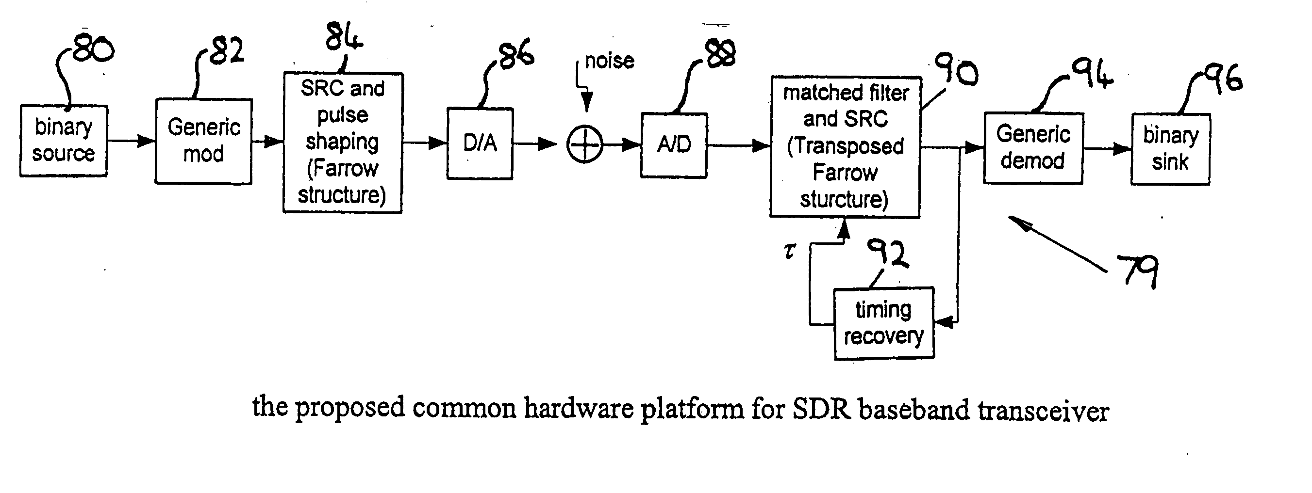
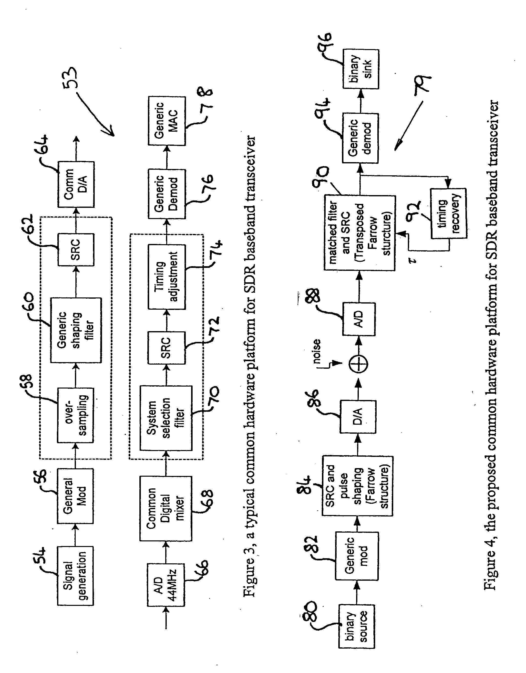
[0045] For simplicity, an indoor wireless communication SDR system is considered, which provides a programmable and dynamically reconfigurable common hardware to implement the physical layer processing of Bluetooth 1.1 and WLAN 802.11g systems. The following has been described, by way of example, and in the context of DSSS mode. However, it should be noted that methods and apparatus according to preferred embodiments of the present invention may be extended to other SDR systems.

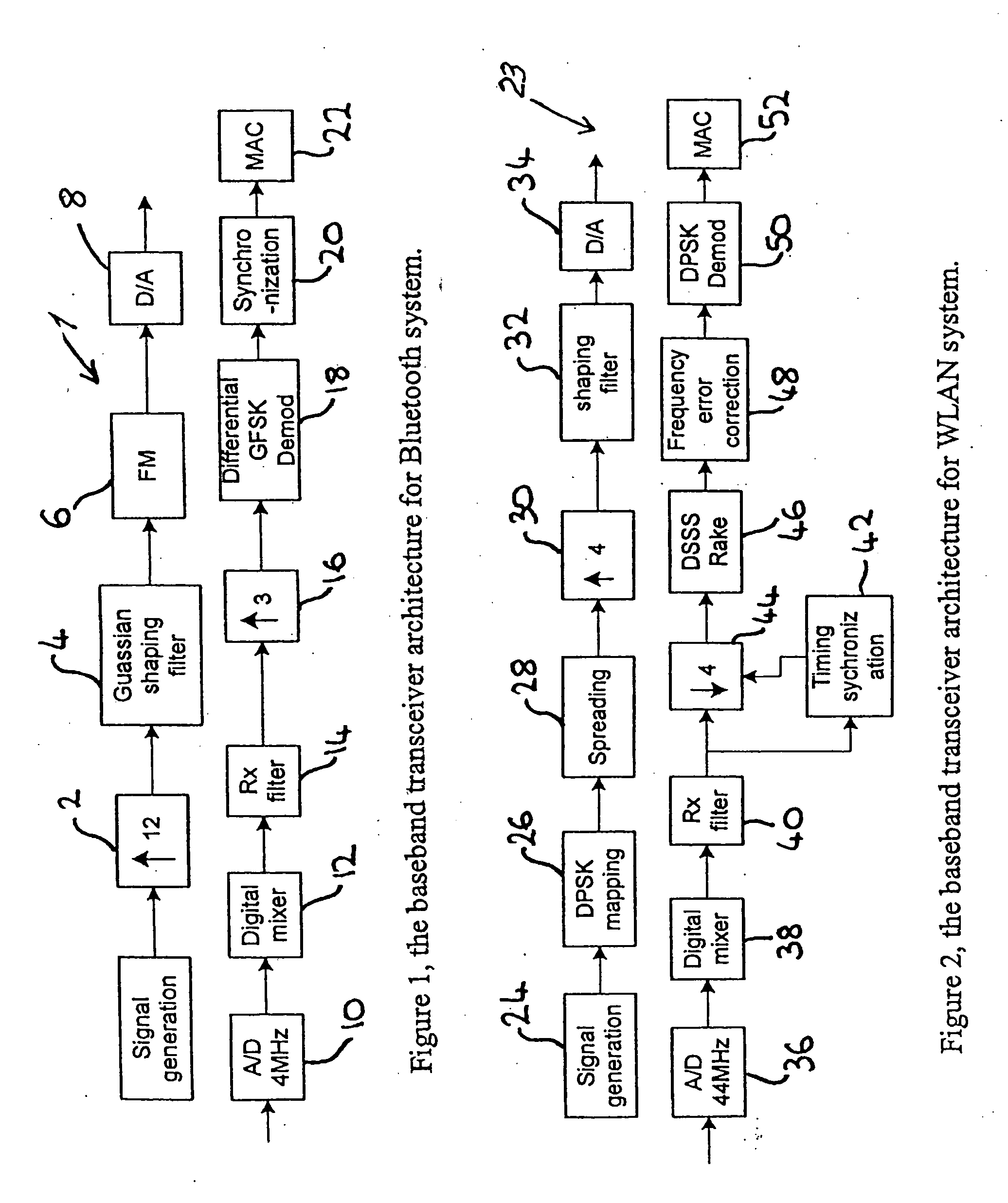
[0046] The transceiver 1 for a conventional Bluetooth 1.1 system is shown in FIG. 1. In the transmitter section of the transceiver 1, the incoming digital signal (which may be generated by a signal generator) is passed to an up-sampling stage 2 in which the bit rate of the signal is raised. The signal is then passed to a pre-modulation Gaussian low pass filter 4 which is required for GFSK modulation systems, to reduce the frequency discontinuity and to improve the spectrum utilization. The output of the filt...


PUM


Abstract

A receiver for a software defined radio system comprises an input stage for receiving a transmitted signal, an analogue-to-digital converter having a sample rate, a filter matched to the received transmitted signal, and a sample rate converter for converting the digital signal output from the filter from an input sequence having the sample rate of the analogue-to-digital converter to an output sequence having an output sample rate defined by the received transmitted signal. The input and output sequences comprise respectively a number of input samples and a number of output samples. A controller controls the output sample rate and a demodulator coupled to the output of the sample rate converter recovers the transmitted signal. The sample rate converter is implemented by a transposed Farrow structure. The controller is arranged to reset the output sequence from the sample rate converter when any one of said number of input samples and any one of said number of output samples pass through coincidence in time.

Description

FIELD OF THE INVENTION [0001] The present invention relates to methods for processing a received signal in a software defined radio (SDR) system, a transceiver for an SDR system and a receiver for an SDR system. BACKGROUND OF INVENTION [0002] Software-defined radios require a programmable and dynamically reconfigurable hardware to implement the physical layer processing of multiple communication systems. Software-defined radio terminals must be able to process many various communications standards. These standards generally employ different data rates and use different master clocks. Hence, sample rate conversion (SRC) should be introduced to the signal processing of digital communication transceivers for use as software-defined radio systems. [0003] A number of SRC solutions have been proposed, for example by Tim Hentschel and Gerhard Fettweis in “Sample rate conversion for software radio”, IEEE Communication Magazine, August 2000, pp142-150, by Tim Hentschel, Matthias Henker and G...

Claims


Application Information

Patent Timeline
IPC IPC(8): H04B1/40H04L27/06
CPCH04B1/40H04B1/0003
Inventor LI, WENZHEN
Owner OKI TECHNO CENT SINGAPORE PTE
Why Eureka
Try Eureka