Tool

a head alignment and guide technology, applied in the field of tools, can solve the problems of re-formation of the bone, endangering the function of the alignment guide, and further erosion, and achieve the effect of stabilising the alignment guid

Inactive Publication Date: 2005-11-03
FINSBURY DEV
View PDF30 Cites 270 Cited by
  • Summary
  • Abstract
  • Description
  • Claims
  • Application Information

AI Technical Summary

Benefits of technology

[0035] The cannulated rod, or where the rod is absent, the collar, will in use, enable the surgeon to position a guide wire or a drill onto the head of the femur or where an aperture has already been formed in the head, into the head of the femur. In one arrangement the collar and/or the cannulated rod where present may have a slot extending along at least a part of the length of the rod to assist in removing the collar and/or rod from the guide wire once it is in position. Where present

Problems solved by technology

Diseases such as rheumatoid- and osteo-arthritis can cause erosion of the cartilage lining of the acetabulum so that the ball of the femur and the hip bone rub together causing pain and further erosion.
Bone erosion may cause the bones themselves to attempt to compensate for the erosion which may result in the bone being reshaped.
This miss

Method used


Image

  • Tool
  • Tool
  • Tool

Examples


Embodiment Construction

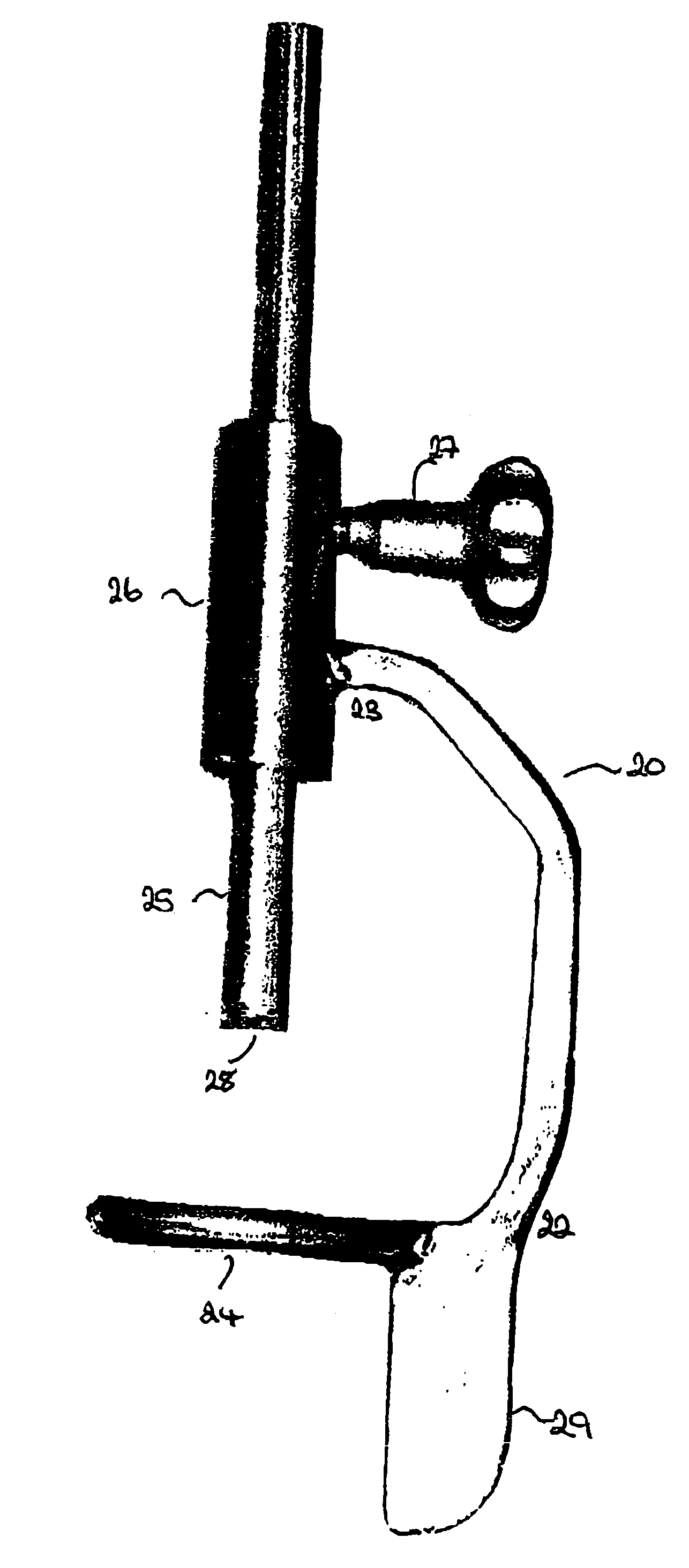
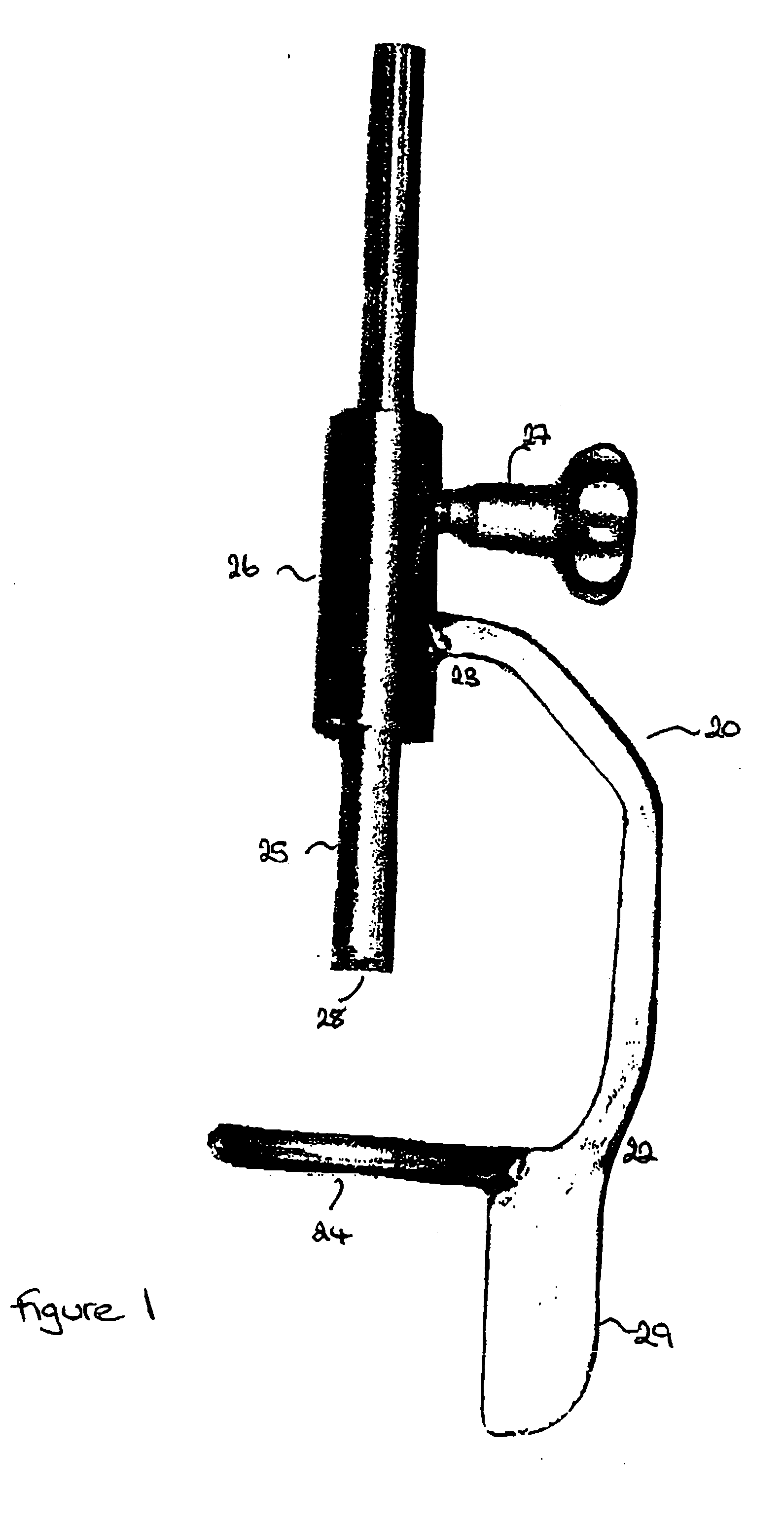
[0101] As illustrated in FIG. 1, the alignment guide 20 of one embodiment of the present invention comprises a support arm having a distal 22 and a proximal 23 end. A ring 24 is located at the distal end of the arm and extends therefrom such that it is at right angles to the plane of the arm. However, it will be noted that the arm is shaped to allow the arm, in use, to fit around the femoral head. A cannulated rod 25 is a sliding fit in a collar 26 located at the proximal end of the support arm. The rod 25 is situated such that the cannula is directly above the centre of the ring. A locking screw 27 is provided to enable the rod 25 to be clamped in the desired position. Teeth 28 are provided on the end of the rod which in use will come into contact with the femoral head.

[0102] A flag 29 may be present to assist the surgeon to visually confirm that the alignment guide is in the desired position.

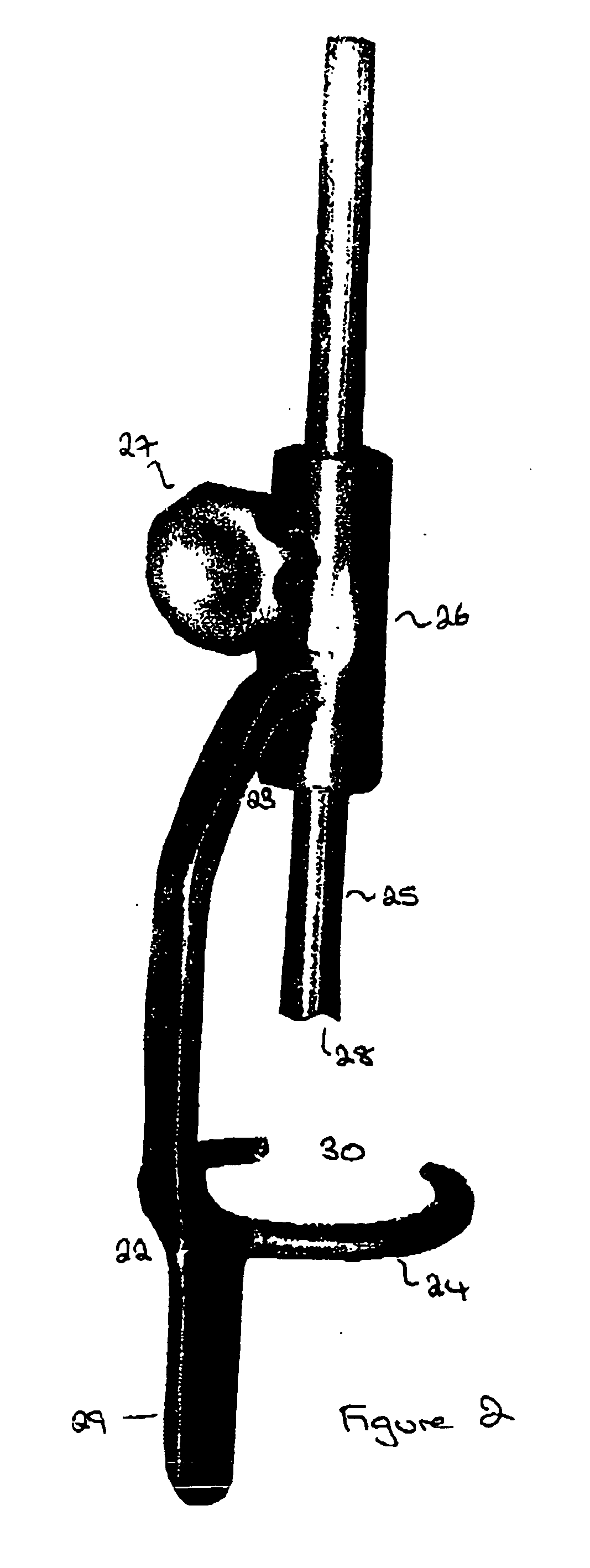
[0103] The alignment of the various components can be seen in FIG. 2. In the illustrated...


PUM


Abstract

An alignment guide for use in femoral head surgery comprising: a support arm having a proximal and a distal end; a ring located at the distal end of the support arm and angled to the plane of the support arm; and a collar located at the proximal end of the support arm, the support arm being configured such that the axis of the bore of the collar is located above the ring.

Description

FIELD OF THE INVENTION [0001] The present invention relates to a tool for use in hip resurfacing operations. More particularly, it relates to a head alignment guide. BACKGROUND OF THE INVENTION [0002] The efficient functioning of the hip joints is extremely important to the well being and mobility of the human body. Each hip joint is comprised by the upper portion of the upper leg bone (femur) which terminates in an offset bony neck surmounted by a ball-headed portion which rotates within a socket, known as the acetabulum, in the pelvis. Diseases such as rheumatoid- and osteo-arthritis can cause erosion of the cartilage lining of the acetabulum so that the ball of the femur and the hip bone rub together causing pain and further erosion. Bone erosion may cause the bones themselves to attempt to compensate for the erosion which may result in the bone being reshaped. This misshapen joint may cause pain and may eventually cease to function altogether. [0003] Operations to replace the hi...

Claims


Application Information

Patent Timeline
IPC IPC(8): A61B17/15A61B17/17A61B17/32A61B19/00
CPCA61B17/15A61B2019/461A61B17/175A61B2090/061
Inventor TUKE, MICHAEL A.WOZENCROFT, ROBERT MICHAELSCOTT, GARETH
Owner FINSBURY DEV
Why Eureka
Try Eureka