Cutting, profiling, and edge-preparing apparatus

a technology of profiling and edge preparation, which is applied in the direction of metal working equipment, manufacturing tools, portable lathes, etc., can solve the problems of star wheel shock, operator of the apparatus in danger of being caught in the moving and contacting parts of the apparatus, and the revolving unit falling off the apparatus, etc., to achieve the effect of easy formation and high accuracy

Inactive Publication Date: 2005-11-10
MORI KENICHI
View PDF7 Cites 26 Cited by
  • Summary
  • Abstract
  • Description
  • Claims
  • Application Information

AI Technical Summary

Benefits of technology

[0019] Since the movement of the tool is controlled by the above referenced templates and since the position, direction, and orientation of the tool is automatically changed as the tool is advanced and retracted, a contact area of the tool with the pipe is minimized, and the edge of the pipe can readily be formed in any shape with ease and at high accuracy. In contrast, conventional edge-preparing apparatus enable a cutting direction along only one axis, and the tool needs to have a shape according to the shape desired for the machined pipe edge since the shape of the pipe edge is determined by the shape of the tool. This problem is overcome with the present invention, and a pipe edge of any desired shape can be formed with the present invention utilizing standard cutting tools.

Problems solved by technology

Consequently, the star wheel comes into contact with the pin and the star wheel is subjected to shocks generated by the collision when the apparatus operates.
Accordingly, the operator of the apparatus is in danger of being caught in the moving and contacting parts of the apparatus.
Moreover, there is a possibility that the revolving unit will fall off the apparatus due to the impact of the collisions and shocks, and machining accuracy is reduced.
Thus, the tool feed mechanism of the conventional apparatus is unable to feed the tools in a rapid-feed mode and / or to return the tools in a rapid-return mode.
However, it is difficult to accurately mount the tool holders on the apparatus.
A cutting edge of a tool that has a greater amount of radial projection than that of the other is subjected to greater loading, and it is possible that the tool will break unless errors in the respective amounts of radial projection of the tools are adjusted to within the above referenced allowable tolerances.
Therefore, a large load is placed on the apparatus upon the impact of the star wheel on the pin and, sometimes, the apparatus becomes dislocated.
Consequently, machining accuracy is reduced, roughness of the machined surface increases, and a stripe formed in a part of the circumference of the pipe at the completion of machining causes faulty welding.
This unavoidably causes the need to change welding work and welding conditions.
In addition, since cutting volume is large, considerable skill is necessary for this operation and it is difficult to obtain satisfactory edge forming accuracy.
When edge preparation is conducted on an outer surface of a pipe, it is especially difficult to control the thickness of the relatively thin lip of the desired edge profile.
In addition, since cutting volume is large, considerable skill is necessary for this operation, and it is difficult to obtain satisfactory edge forming accuracy.
However, it is difficult for a conventional edge-preparing apparatus to realize such high-accuracy machining.
However, this is labor-consuming, and there is still great difficulty in obtaining the desired accuracy.

Method used


Image

  • Cutting, profiling, and edge-preparing apparatus
  • Cutting, profiling, and edge-preparing apparatus
  • Cutting, profiling, and edge-preparing apparatus

Examples


first embodiment

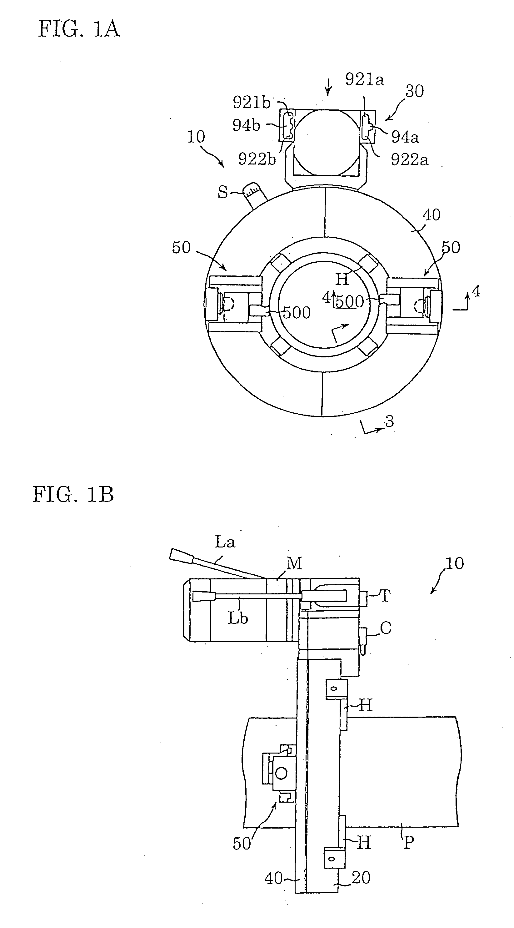
[0043]FIG. 1 illustrates a cutting apparatus 10 according to the present invention. FIG. 1A is a front elevation of the cutting and edge-preparing apparatus 10, and FIG. 1B is a side elevation of the cutting and edge-preparing apparatus 10 mounted on a pipe “P”. The cutting and edge-preparing apparatus 10 is of a two-piece divided type construction similar to conventional cutting and edge-preparing apparatus.

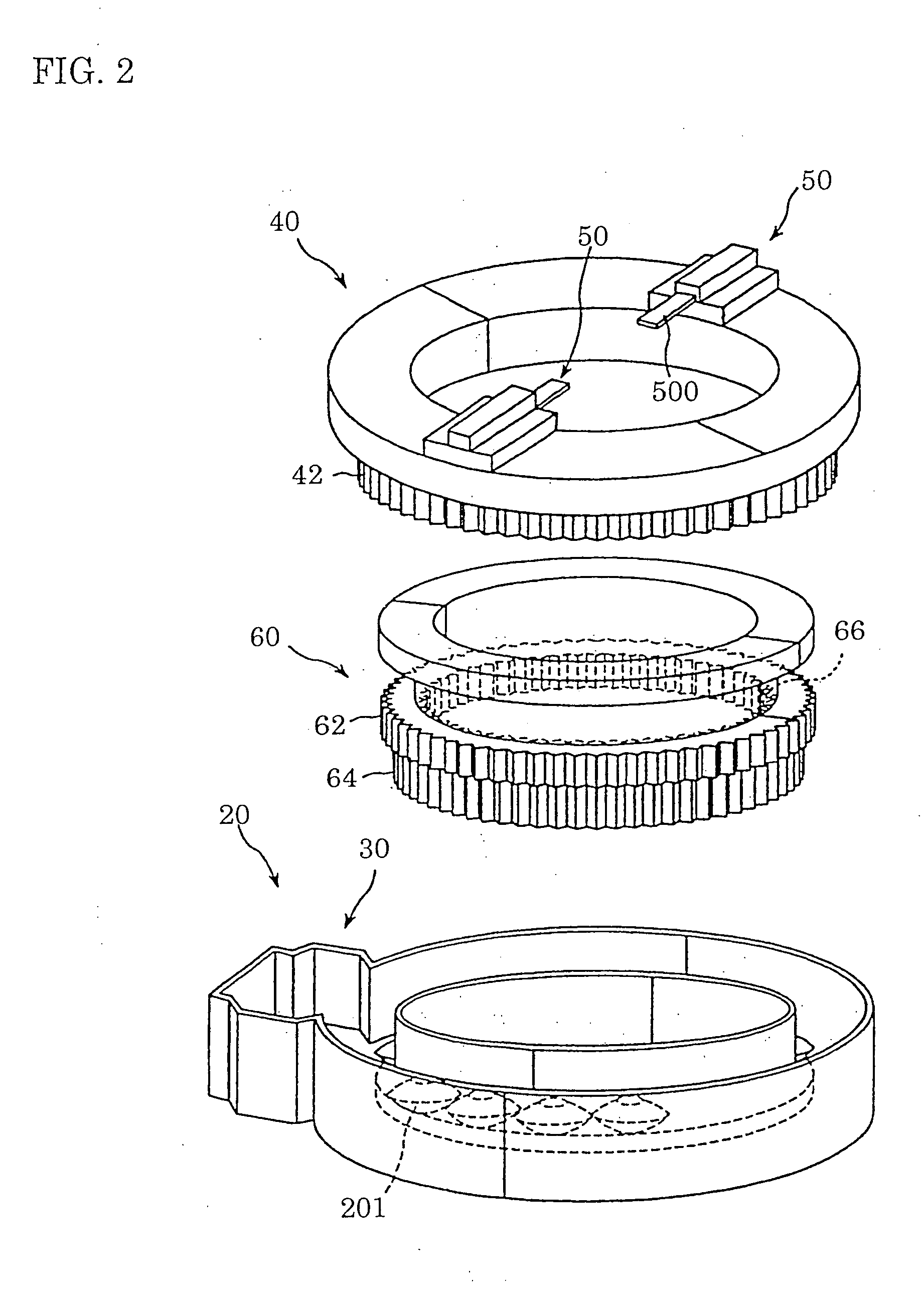
[0044] The apparatus 10 includes a housing 20, a gearbox 30, a faceplate 40, tool holders 50, and a motor “M”. A plurality of feet “H” project radially inward from the inner circumference of the housing 20 and hold the cutting and edge-preparing apparatus 10 on the pipe “P”. The housing 20 contains a speed-changing compound ring gear 60 and has a front surface on which the faceplate 40 is rotatably supported. A pair of tool holders 50 are utilized to mount tools 500 to the faceplate 40 such that the tools 500 are mounted at diametrically opposite locations. The tools 500 illustr...

second embodiment

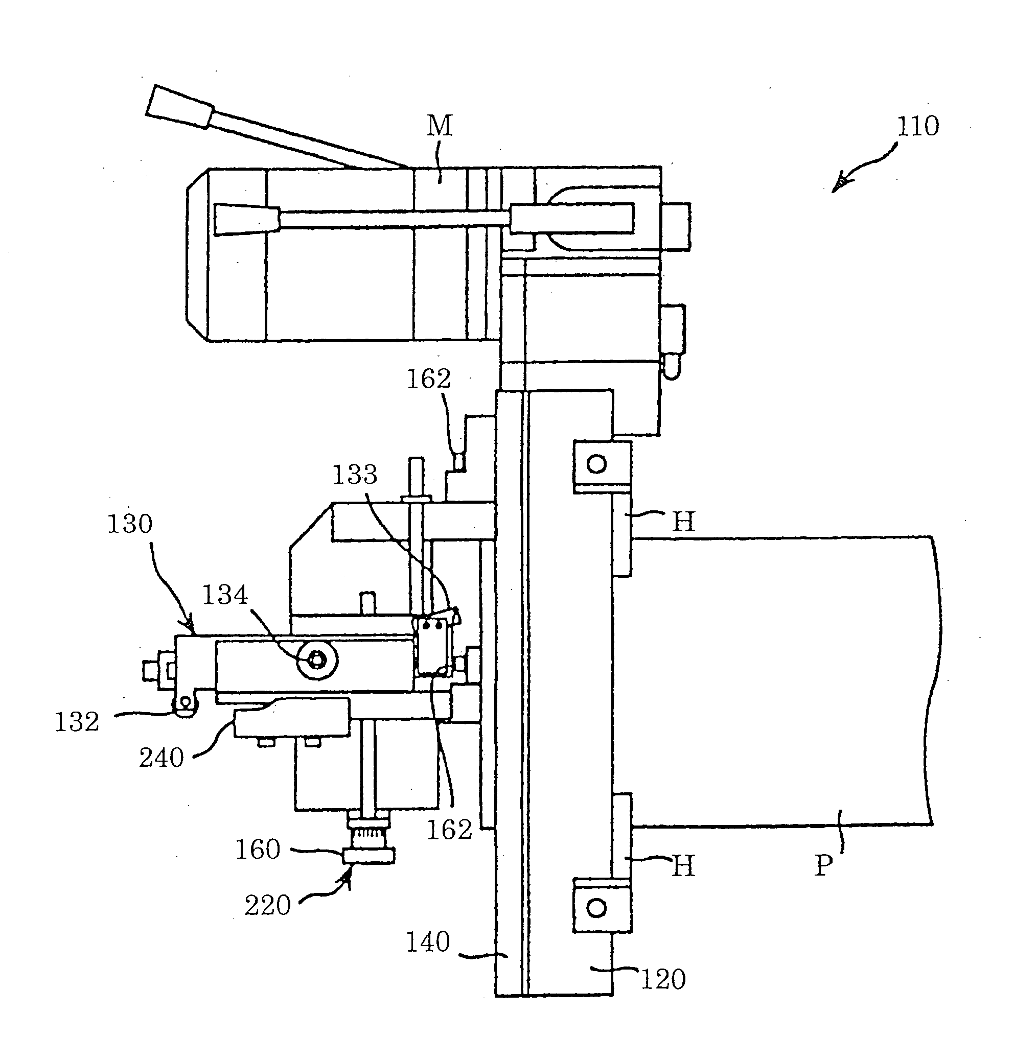
[0073] Turning to a second embodiment according to the present invention, a profile machining apparatus 110 for edge-preparation of a pipe is shown in FIGS. 9-15. FIG. 9A shows a front view of the profiling apparatus 110, and FIG. 9B shows a side view of the edge-preparing apparatus 110 mounted on a pipe. For ease of illustration, a manual feed apparatus 200 is shown in FIG. 9A, but not in FIG. 9B. The profile machining apparatus 110 is used to form an inner surface grinding section and a recess in an inner surface of a pipe. For example, see the profiles illustrated in FIGS. 21A, 21B, and 21C.

[0074] As shown in FIGS. 9A and 9B, the profile machining apparatus 110 includes a housing 120 mounted on a pipe “P”, a faceplate 140 rotatably mounted on a front surface of the housing 120, and a tool holder 220 which is mounted on the faceplate 140 and holds a tool 133. The tool holder 220 is mounted on the faceplate 140 with lock screws 162. When the faceplate 140 rotates and the relative v...

third embodiment

[0084] Turning to a third embodiment according to the present invention, a profile machining apparatus 412 is illustrated in FIGS. 16-20. A front view of the profile machining apparatus 412 is illustrated in FIG. 16A and a side view of the apparatus mounted on a pipe is illustrated in FIG. 16B. A manual feed apparatus 200 (discussed below in greater detail) is shown in FIG. 16A, but not in FIG. 16B for illustrative purposes. The profile machining apparatus 412 can be used to form a lip and a groove in an outer surface of the pipe “P”. As shown in FIGS. 16A and 16B, the profile machining apparatus 412 includes a housing 420 mounted on a pipe “P”, a faceplate 440 rotatably mounted on a front surface of the housing 420, and a tool holder 422 mounted on the faceplate 440 and holding a tool 433. When the tool holder 422 is mounted and rotated on the faceplate 440 and a relative velocity between the faceplate 440 and the ring gear (not shown) therein is generated, an outer surface of the ...


PUM

PropertyMeasurementUnit
diametersaaaaaaaaaa
poweraaaaaaaaaa
timeaaaaaaaaaa

Abstract

An apparatus for cutting and/or profile machining an edge of a pipe is provided. The apparatus includes a housing, a rotatable faceplate mounted on a front surface of the housing, and a tool holder mounted on the faceplate and holding a cutting tool. In a first embodiment, a cutting apparatus includes gearing that permits the tool holder to be moved relative to a surface of a pipe in a rapid-feed mode, a slow-feed mode and a rapid-return mode. In second and third embodiments, a profile machining apparatus includes a carriage having a profiling roller or shaft that advances (or retracts) relative to a pipe along a path defined by a template. The carriage to which the cutting tool is mounted is pivoted about a support shaft permitting the carriage and tool to change its angle and orientation relative to the pipe while advancing or retracting.

Description

BACKGROUND OF THE INVENTION [0001] The present invention relates to a cutting, profiling, and edge-preparing apparatus and, more particularly, to an apparatus for cutting a pipe to be used, for instance, in a nuclear power plant, and / or for preparing an edge of the pipe for welding. [0002] A cutting and edge-preparing apparatus has been used for cutting a pipe and preparing an edge of a pipe for welding. The conventional cutting and edge-preparing apparatus is mounted on an outer surface of a pipe, i.e., workpiece, to cut the pipe and to prepare the edge of the pipe for welding. The apparatus typically includes a stationary unit, a revolving unit, and cutting tools. The stationary unit is fixedly mounted on the pipe, and the revolving unit is mounted on a front surface of the stationary unit such that it can rotate about the outer surface of the pipe. A pin is fixed to the stationary unit so as to project radially inward. [0003] The revolving unit holds a tool holder to which a plur...

Claims


Application Information

Patent Timeline
Patent Type & Authority Applications(United States)
IPC IPC(8): B23B5/16B23B3/22B23B3/26
CPCB23B3/26Y10T82/22B23B2260/004B23B5/16
Inventor KAWASHIMA, SHINJI
Owner MORI KENICHI
Why Eureka
Try Eureka