Millivolt damper control device

a control device and millivolt technology, applied in the direction of domestic stoves or ranges, ways, heating types, etc., can solve the problems of toxic products, invisible products of incomplete gas combustion, leakage of air into the home, etc., and achieve the effect of high quality

Inactive Publication Date: 2005-11-10
FLUE SENTINEL
View PDF8 Cites 28 Cited by
  • Summary
  • Abstract
  • Description
  • Claims
  • Application Information

AI Technical Summary

Benefits of technology

[0006] In accordance with a first aspect, a millivolt damper control device comprises a damper positioned in a flue, wherein the damper is movable between a closed position where the flue is blocked and an open position, a thermoelectric device having an input voltage, a battery having a voltage, and a controller comprising a comparator circuit which compares the input voltage with a reference voltage based upon the voltage of the battery. When the input voltage is greater than or equal to the reference voltage, the comparator circuit transmits a damper signal to move the damper to the open position.
[0007] From the foregoing disclosure and the following more detailed description of various preferred embodiments it will be apparent to those skilled in the art that the present invention provides a significant advance in the technology and art of damper control devices. Particularly significant in this regard is the potential the invention affords for providing a high quality damper control device for fireplaces and other outside and remote applications. Additional features and advantages of various preferred embodiments will be better understood in view of the detailed description provided below.

Problems solved by technology

Such a connection can result in leakage of air into the home.
An operator has to remember to open the damper prior to starting a fire in the fireplace, or else the products of combustion would become trapped in the home.
However, the products of incomplete gas combustion can be invisible and toxic (CO2, CO, for example).
Because of this potentially hazardous situation, ventilation of air has been required for gas fireplaces where dampers have been used.
Further, in some places dampers were not allowed to be used in combination with gas fireplaces.
However, fireplace dampers may be subjected to significantly higher load requirements than dampers in furnaces.
Further, for fireplace dampers, resistive losses increase with the increased distance between the pilot light and the damper.

Method used


Image

  • Millivolt damper control device
  • Millivolt damper control device
  • Millivolt damper control device

Examples


Embodiment Construction

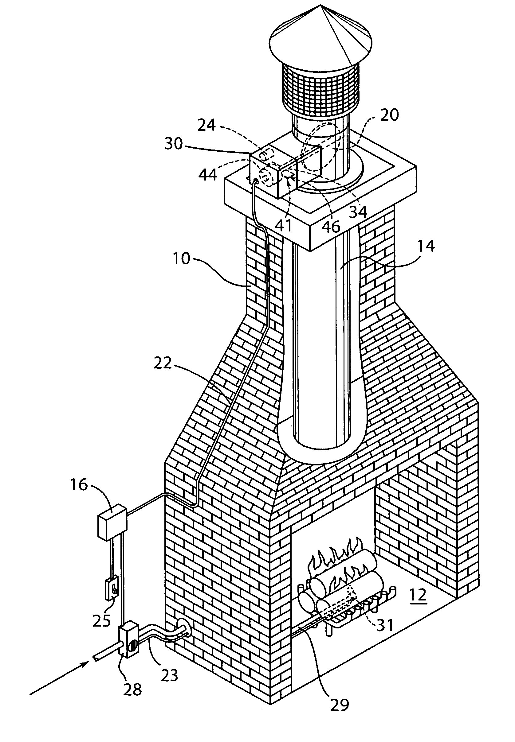
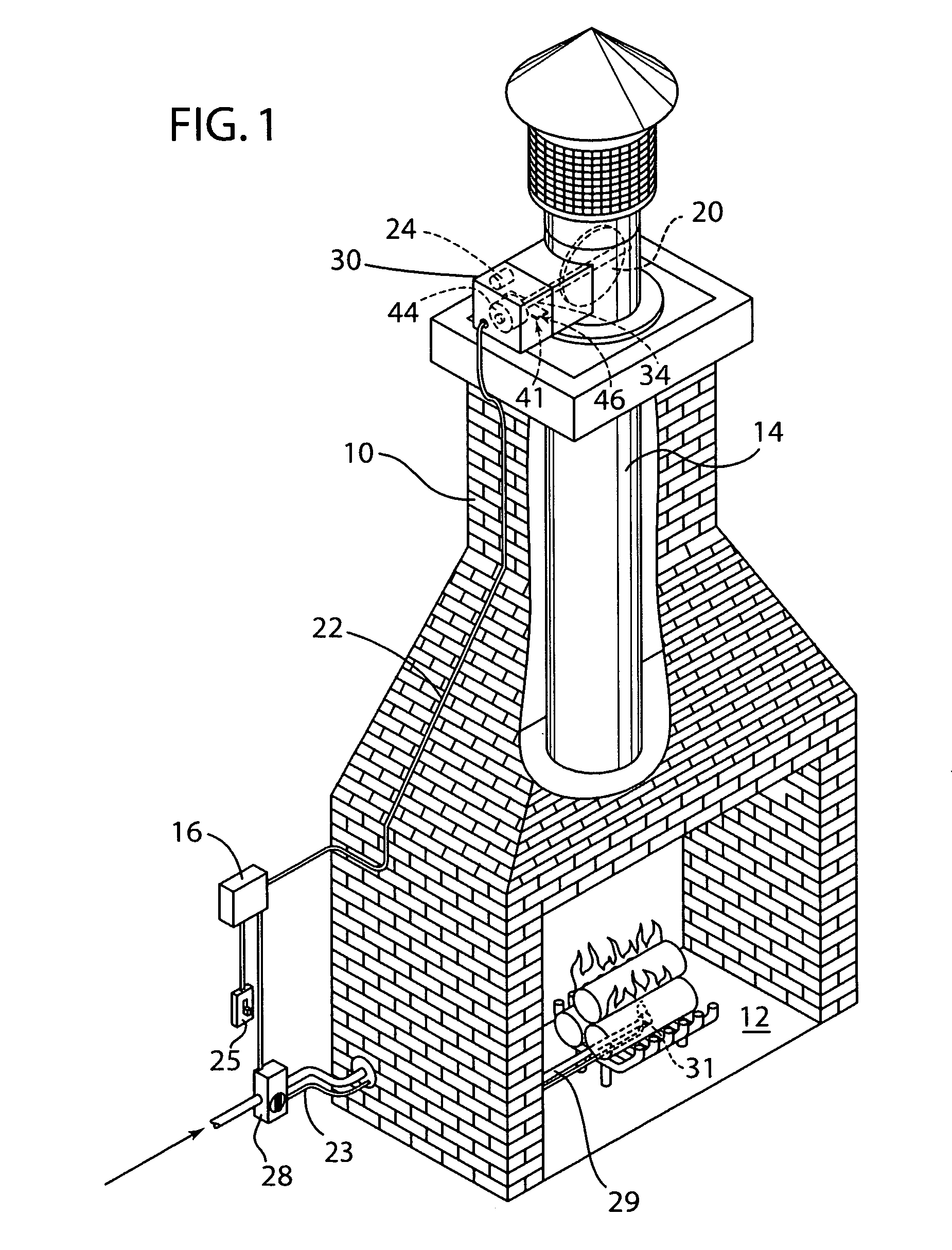
[0013] It will be apparent to those skilled in the art, that is, to those who have knowledge or experience in this area of technology, that many uses and design variations are possible for the damper control device disclosed here. The following detailed discussion of various alternative and preferred features and embodiments will illustrate the general principles of the invention with reference to a damper control device for a gas fireplace. Other embodiments suitable for other applications, such as wood burning fireplaces, will be apparent to those skilled in the art given the benefit of this disclosure.

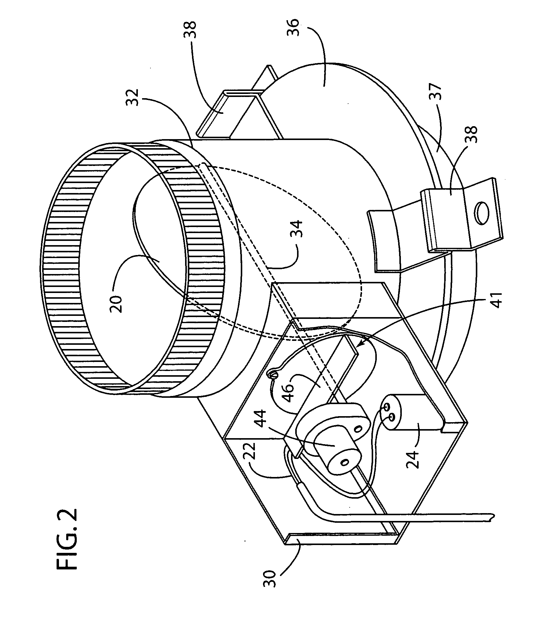
[0014] Turning now to the drawings, FIG. 1 shows a chimney 10 having a fireplace 12, a flue 14 which receives products of combustion from the fireplace, and a damper 20. In the preferred embodiment shown here, the fireplace 12 is a gas fireplace, with the gas supplied by a gas line 29. The damper 20 is movable by electric motor 44 via rotatable shaft 34 between a closed position wh...


PUM


Abstract

A millivolt damper control device comprises a damper movable between a closed position where a flue is blocked and an open position, a thermoelectric device having an input voltage, a battery having a voltage, and a controller comprising a comparator circuit which compares the input voltage with a reference voltage based upon the voltage of the battery. When the input voltage is greater than or equal to the reference voltage, the comparator circuit transmits a damper signal to move the damper to the open position.

Description

RELATED APPLICATION [0001] This application claims priority benefit of U.S. provisional patent application No. 60 / 568,003 filed on May 4, 2004.FIELD OF THE INVENTION [0002] This invention relates to a device for controlling a damper, and more particularly to a damper control device for a fireplace. BACKGROUND OF THE INVENTION [0003] Many homes today have fireplaces where a flue in a chimney connects the outside air to the fireplace. Such a connection can result in leakage of air into the home. A damper can be positioned in the flue and used to keep the air out. The damper is movable between a closed position which prevents air from leaking into or out of the home, to an open position which allows air to flow and exhaust products of combustion to flow out of the home. Such known dampers are controlled by a chain, handle, lever or the like. An operator has to remember to open the damper prior to starting a fire in the fireplace, or else the products of combustion would become trapped ...

Claims


Application Information

Patent Timeline
Patent Type & Authority Applications(United States)
IPC IPC(8): F23L3/00F23L11/00F23L13/00F23L13/02F23N3/02F24B1/00F24B1/189F24C15/00
CPCF23L11/005F23L13/02F23N3/02F24C15/001F23N2035/04F24B1/1895F23N2023/14F23N2223/14F23N2235/04
Inventor WEISS, CORY A.
Owner FLUE SENTINEL
Why Eureka
Try Eureka