Operation input device and method of operation input

a technology of operation input and input device, which is applied in the direction of mechanical pattern conversion, instruments, cathode-ray tube indicators, etc., can solve the problems of troublesome work, device user-unfriendly, and inconvenient use of different devices for different operations, so as to facilitate operation input without reducing the pointing area

Active Publication Date: 2005-11-10
ALPINE ELECTRONICS INC
View PDF11 Cites 77 Cited by
  • Summary
  • Abstract
  • Description
  • Claims
  • Application Information

AI Technical Summary

Benefits of technology

[0014] In order to solve the above-described problems, an object of the invention is to eliminate the necessity to move a pointing device such as a finger to a predetermined fixed space, thereby improving usability.

Problems solved by technology

All these operation input devices are contact-type input devices which are operated by actually being touched by an operator, and require troublesome work.
For example, when the operator activates application software on a computer system to work thereon, the operator must use the keyboard for character input or the like and use the mouse or the trackball for specifying positions, and such utilization of different devices for different operations is quite inconvenient.
In addition, in order to operate a vehicle-mounted navigation system, the driver must stop the vehicle for safety, release his / her hands from the steering wheel, and operate the joystick of the remote controller or the touch panel each time, which is quite troublesome.
However, according to the technology described in the above-described patent document, the position in space for the operation input is limited to a plane scanned by the infrared ray, and hence the pointing device such as a finger must be moved to the above-described spatial plane each time.
Therefore, the operator must move the pointing device such as a finger to the predetermined spatial plane irrespective of the position of the operator, and hence this device is very user-unfriendly.
Yet, the range which the operator can reach depends on the physical constitution and hence there arises a problem that an operator having a smaller body may have a difficulty to execute the input operation depending on the position of the spatial plane.
There is also a problem such that since the spatial plane is determined to have an absolute positional relation with respect to the display screen, the angle with respect to the spatial plane may vary with the position of the operator, and hence errors may occur in the operation input.
There is another problem in the technology described in the above-described patent document in that there is no way to differentiate the movement of the pointing device between a movement corresponding to the operation input and other movements.
Also, the contact-type and non-contact type operation input devices described above both can execute the operation input only for an object displayed on the display screen, and an object which is assumed to be outside the display screen cannot be operated directly.
Therefore, the operator must perform a very troublesome operation, that is, repeat a scrolling operation until the estimated point is displayed on the screen.
However, when the size of the indicating area is increased, the area which displays main content information such as the map or movie is decreased, whereby the content information cannot be seen optimally.
In contrast, when the size of the indicating area is reduced in order to avoid the above-described problem, accuracy of an indicating action done by the finger or the like is required, which causes a problem that the operability is degraded.
Such a problem becomes obvious when the size of the display screen is not large, such as in the navigation system.

Method used


Image

  • Operation input device and method of operation input
  • Operation input device and method of operation input
  • Operation input device and method of operation input

Examples


first embodiment

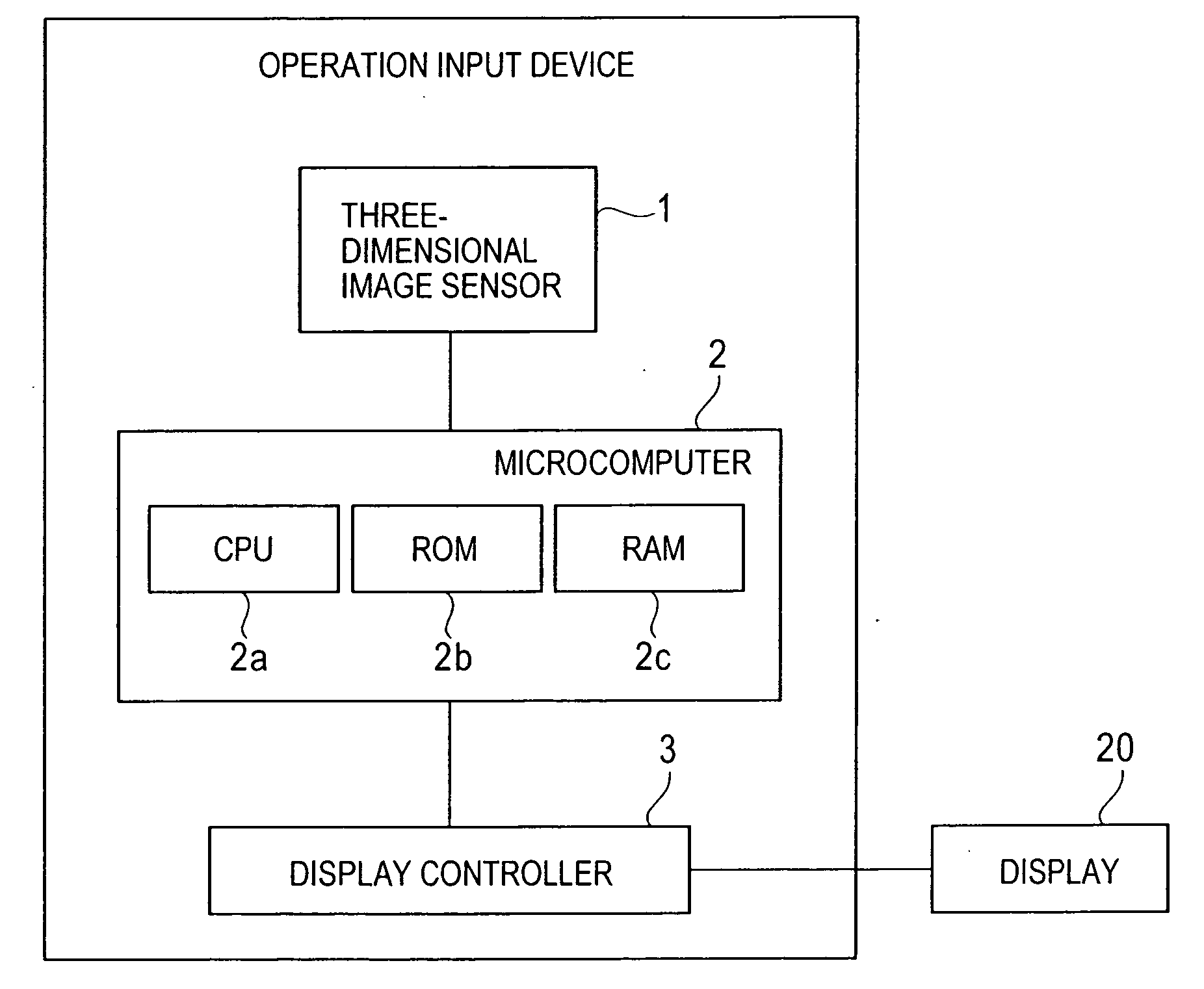
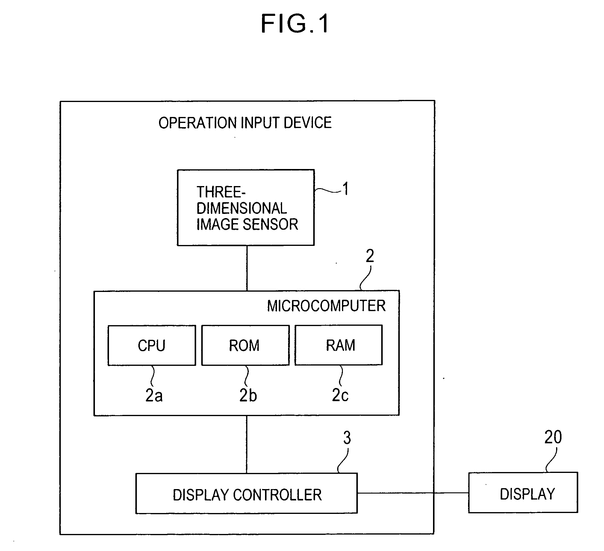
[0049] Referring now to the drawings, an embodiment of the present invention will be described. FIG. 1 is a drawing showing an example of a structure of an operation input device according to a first embodiment. As shown in FIG. 1, the operation input device according to the first embodiment includes a three-dimensional image sensor 1 as a position detecting means, a microcomputer 2 including a CPU 2a, a ROM 2b and a RAM 2c, and a display controller 3 as a display controlling means for controlling the display of a display 20.

[0050] The three-dimensional image sensor 1 is for detecting a three-dimensional position of an object in a space. For example, the distance to the object (the relative position of the object) is detected by irradiating a beam to the object and measuring the beam which is reflected back therefrom. For the three-dimensional image sensor 1, for example, a known technology which is disclosed in U.S. Pat. No. 6,515,740 may be applied. With the technology described ...

second embodiment

[0073] A second embodiment of the invention will now be described. FIG. 6 is a drawing showing an example of the structure of the operation input device according to the second embodiment. In FIG. 6, components represented by the same reference numerals have the same functions, and redundant description will be omitted.

[0074] As shown in FIG. 6, the operation input device according to the second embodiment includes two three-dimensional image sensors 1-1, and 1-2. The three-dimensional image sensor 1-1 is used for detecting the three-dimensional position of the pointing device 34 in the pointing space 32 as in the first embodiment. The other three-dimensional image sensor 1-2 is used for detecting the three-dimensional position of the operator's eye.

[0075]FIG. 7 is a conceptual drawing for explaining the pointing space 32 according to the second embodiment. As shown in FIG. 7, in the second embodiment, the predetermined reference point 31 is set to the position of the operator's e...

third embodiment

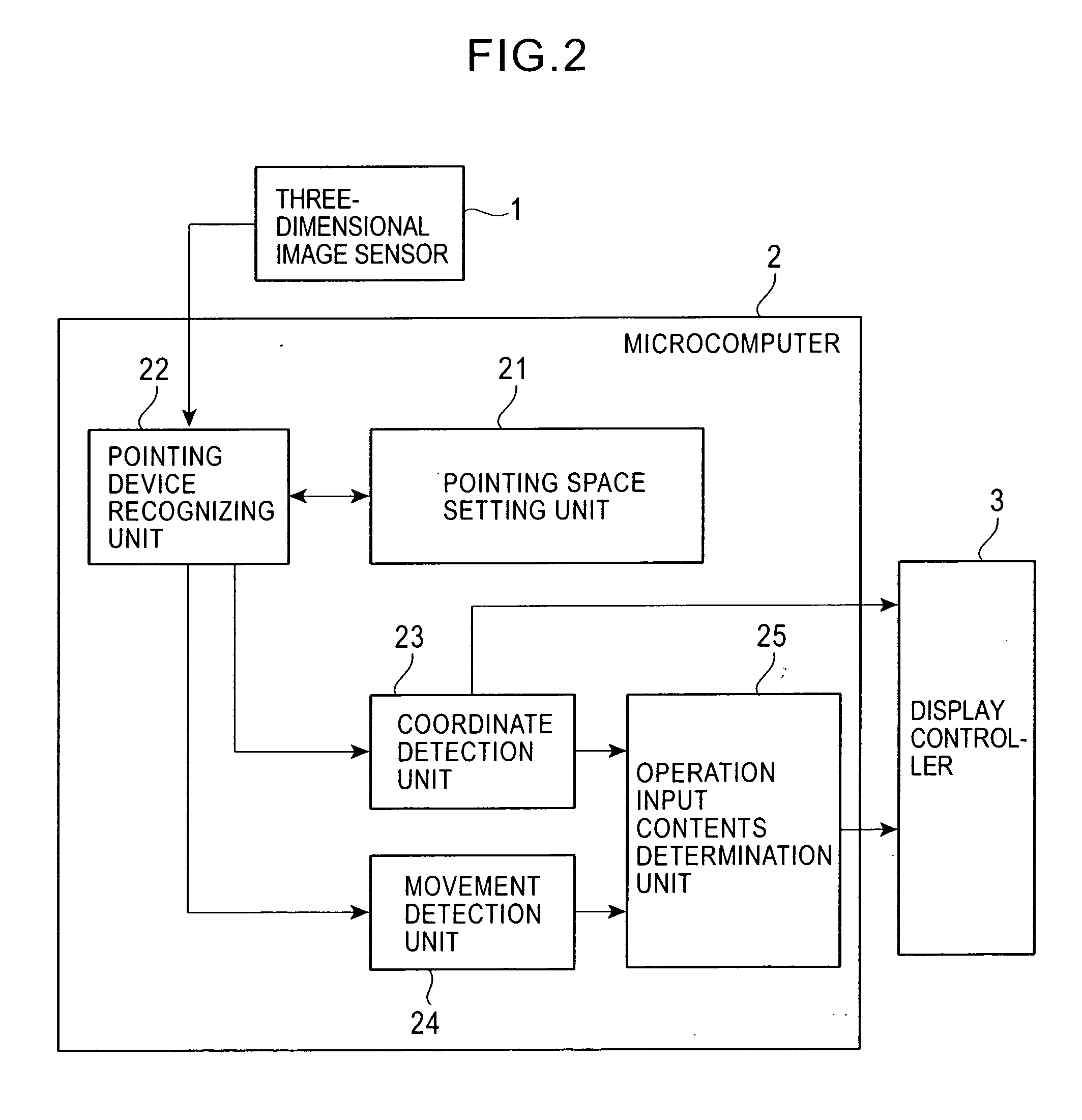
[0083] A third embodiment of the present invention will now be described. In the third embodiment, the three-dimensional image sensor 1 is used as the position detection means as in the first embodiment. The functional structure of the microcomputer 2 in the third embodiment is shown in the block diagram in FIG. 10. In FIG. 10, the components represented by the same reference numerals as those shown in FIG. 2 have the same functions, and redundant description will be omitted.

[0084] As shown in FIG. 10, in the third embodiment, a pointing space setting unit 28 having a different function than the pointing space setting unit 21 shown in FIG. 2 is provided as a functional structure of the microcomputer 2. The pointing space setting unit 28 sets the reference point 31 at a position which defines the pointing space 32 so as to allow the operator to operate the pointing device 34 in a natural manner. More specifically, the pointing space setting unit 28 issues an instruction to the displ...


PUM


Abstract

A three-dimensional image sensor for detecting the three-dimensional position of an object, a coordinate detection unit for detecting the coordinate position of an objective point on a display screen based on the position of the object in a virtual pointing space, a movement detection unit for detecting the three-dimensional movement of the object in the pointing space, and an operation input contents determination unit for determining an operation based on the three-dimensional movement or the like of the object are provided, so that the inconvenience of moving a pointing device such as a finger to a fixed spatial plane is avoided by setting the pointing space which can be operated by the pointing device as a pyramid shape defined by connecting the display screen and a reference point.

Description

BACKGROUND [0001] 1. Field of the Invention [0002] The present invention relates to an operation input device and a method of operation input, and is suitable specifically for an operation input device for issuing instructions to a computer system or a navigation system through the input operation by an operator. [0003] 2. Description of the Related Art [0004] In the related art, a wide variety of operation input devices are employed for issuing instructions to a computer system or a navigation system through the input operation by an operator, such as a remote controller including a keyboard, mouse, trackball or joystick, or a touch panel. All these operation input devices are contact-type input devices which are operated by actually being touched by an operator, and require troublesome work. [0005] For example, when the operator activates application software on a computer system to work thereon, the operator must use the keyboard for character input or the like and use the mouse ...

Claims


Application Information

Patent Timeline
Patent Type & Authority Applications(United States)
IPC IPC(8): G06F3/00G06F3/01G06F3/033G06F3/042
CPCG06F3/0304G06F3/011
Inventor ENDOH, KENJIRO
Owner ALPINE ELECTRONICS INC
Why Eureka
Try Eureka