Pressurizing pump device, liquid ejection apparatus and method of controlling pressurizing pump

a technology of pressurizing pump and liquid ejection device, which is applied in the direction of pump control, printing, and printing apparatus, can solve the problems of large printing apparatus, inability to supply stable air pressure to ink cartridge, and inability to remove ink cartridges, etc., and achieves the effect of simple control

Active Publication Date: 2005-11-10
SEIKO EPSON CORP
View PDF6 Cites 37 Cited by
  • Summary
  • Abstract
  • Description
  • Claims
  • Application Information

AI Technical Summary

Benefits of technology

[0064] According to the constitution, when the pressurizing operation is executed, the pressurizing operation is executed by rotating the drive motor in one direction and when the pressurization releasing operation is executed, the pressurization releasing operation is executed by switching rotation of the drive motor rotation in other direction. Therefore, the same drive motor can be used in both of the pressurizing operation and the pressurization

Problems solved by technology

However, when a kind of a printing apparatus mounted with an ink cartridge on a carriage (on-carriage type) is simply mounted with an ink cartridge having a large capacity, the carriage and therefore, the printing apparatus is large-sized and also the carriage per se is applied with a large load.
However, when a diaphragm type pump shown in JP-A-2000-352379 is used, a plurality of pump chambers are present on a plane orthogonal to an axis center of the pump and therefore, the pump is large-sized in a diameter direction to pose a problem that a pressurizing pump and therefore, a printing apparatus is large-sized.
Meanwhile, when inside of the air supply tube is brought into an excessively high pressure state, a stable air pressure cannot be supplied to the ink cartridge.
Further, when inside of the air supply tube space stays in the high pressure state in interchanging the ink cartridge, also a space in the cartridge communicated with the tube is brought into a high pressure state and the ink cartridge is brought into an expanded state and therefore, the ink cartridge becomes difficult to remove.
Further, inside of the air supply tube is released to the atmosphere by opening the pressure control valve when the air supply tube is brought into the excessively high pressure state or when a power source of the printing apparatus is made OFF.
However, when the diaphragm type pump shown in JP-A-2000-35237 is used, in view of a current situation that since a plurality of pump chambers are present on the same plane of the pump,

Method used


Image

  • Pressurizing pump device, liquid ejection apparatus and method of controlling pressurizing pump
  • Pressurizing pump device, liquid ejection apparatus and method of controlling pressurizing pump
  • Pressurizing pump device, liquid ejection apparatus and method of controlling pressurizing pump

Examples


first embodiment

[0091] An explanation will be given of the first embodiment of a pressurizing pump device, a liquid ejection apparatus and a method of releasing a pressurization of a pressurized fluid embodying the invention in reference to FIG. 1 through FIG. 16 as follows.

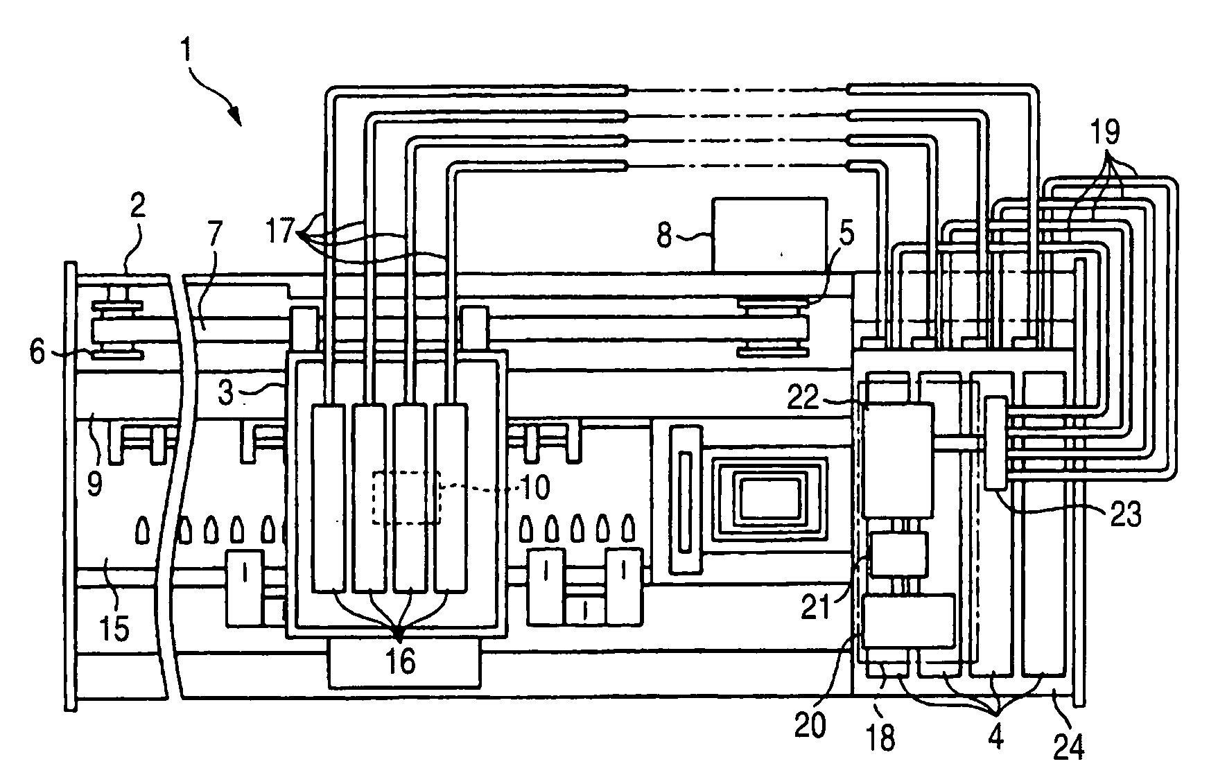
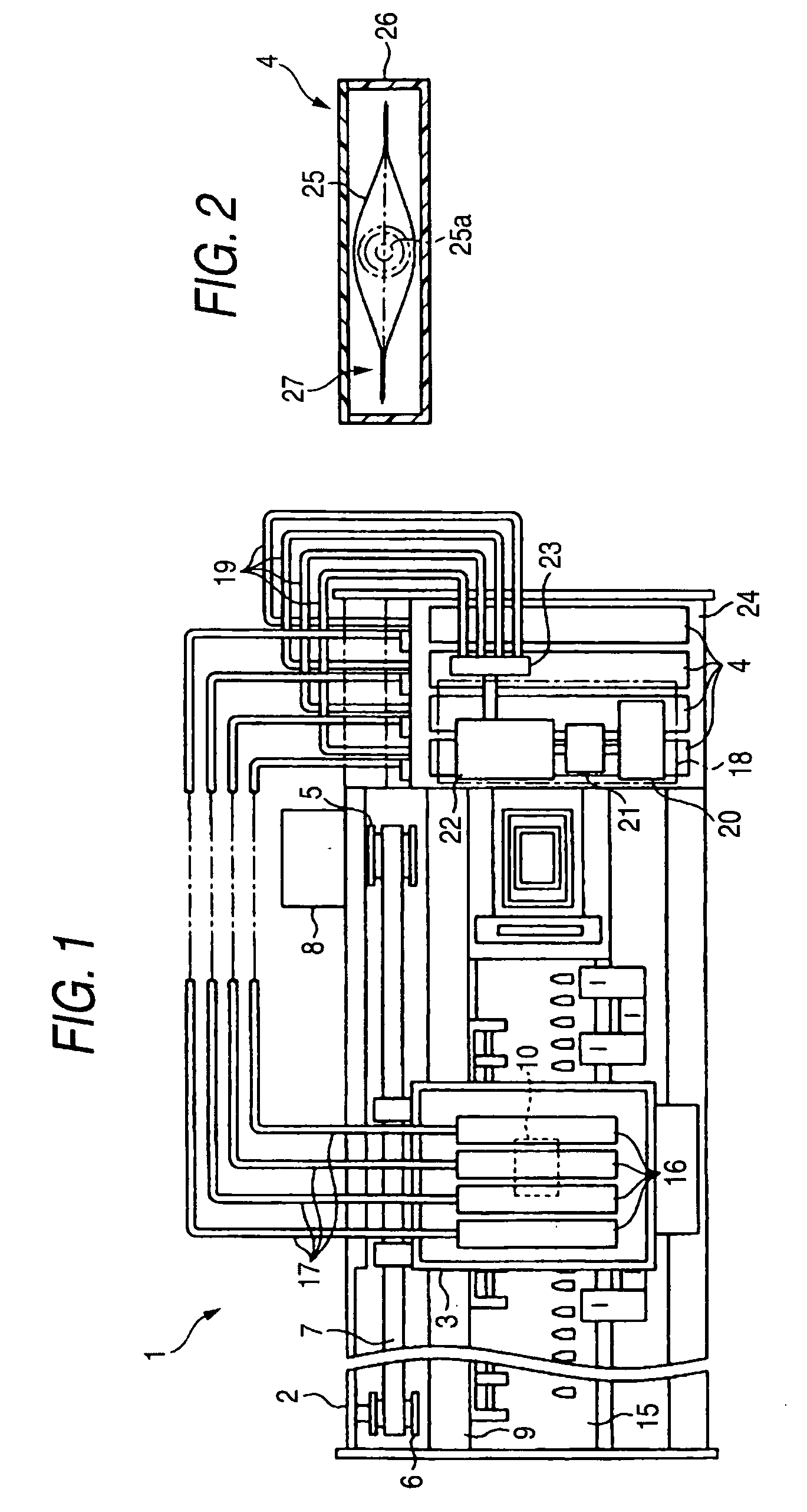
[0092]FIG. 1 is a plane view showing an outline constitution of inside of a case of a printing apparatus 1. The printing apparatus 1 is of an off-carriage including a carriage 3 and an ink cartridge 4 at inside of a main body case 2 and constituting the carriage 3 and the ink cartridge 4 by separate members. The carriage 3 is attached to an endless timing belt 7 expanded by a drive pulley 5 and a driven pulley 6, and is reciprocated to move in a main scanning direction (left and right direction of FIG. 1) in a state of being guided by a guide shaft 9 by driving the timing belt 7 by a carriage motor 8. Further, the printing apparatus 1 corresponds to a liquid ejection apparatus, and the ink cartridge 4 corresponds to a liquid ca...

second embodiment

[0185] An explanation will be given of second embodiment of a pressurization apparatus, a liquid ejection apparatus and a flow path structure of a pressurizing pump embodying the invention in reference to FIG. 17 through FIG. 20 as follows.

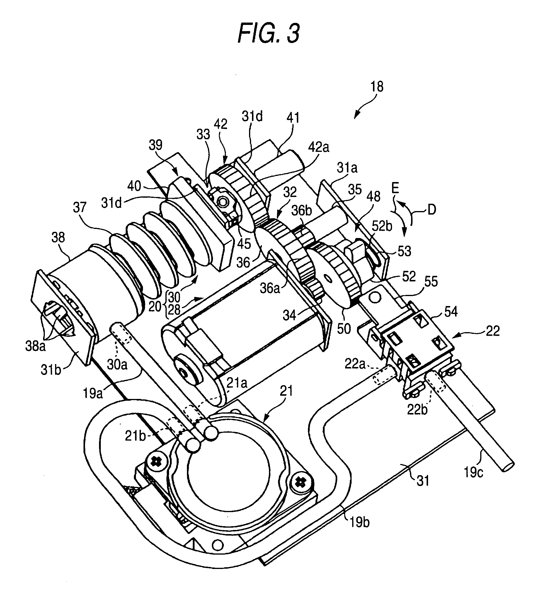
[0186] As shown in FIGS. 17 and 18, the pump portion 130 is provided with a compressing portion 137 having the pump chamber 29 at inside thereof and a seat portion 138 attached to an end portion of the compressing portion 137. The compressing portion 137 includes a diaphragm (bellows) 137a and the diaphragm 137a is fabricated by, for example, blow forming or the like. The diaphragm 137a is capable of being expanded and contracted in a longitudinal direction (arrow mark A direction shown in FIG. 18) by constituting a drive source by the pump motor 28 and a volume of the pump chamber 29 is increased and reduced in accordance with the expanding and contracting operation. Further, the pump motor 28 corresponds to driving means (drive motor) and the g...


PUM


Abstract

In a printing apparatus of an off-carriage type, when a pump motor is rotated regularly for delivering pressurizing air to an ink cartridge, rotation thereof is converted into a linear reciprocating movement of a pressing member by a cam mechanism and a pressurizing operation is executed by repeating to operate to expand and contract a diaphragm. On the other hand, the pump motor is started to rotate inversely, a driven part is rotated by a friction clutch mechanism, and a pressing portion of the driven part is brought into contact with a valve opening lever of an atmospheric release valve. At this occasion, the valve opening lever is pivoted to bring a valve hole into an opened state and pressurizing air is discharged to outside by bringing the atmospheric release valve into an opened state.

Description

BACKGROUND OF THE INVENTION [0001] 1. Field of the Invention [0002] The present invention relates to a pressurizing pump device for discharging a pressurizing fluid by repeating suction and delivery, a liquid ejection apparatus, a flow path structure of a pressurizing pump, a method of stopping driving a pressurizing pump and a method of releasing a pressurization of a pressurizing fluid. [0003] 2. Related Art [0004] In a background art, various kinds of printing apparatus have been developed and according to a kind of a printing apparatus, for example, for office use or for business, a large amount of ink is consumed in accordance with an increase in a printing frequency and therefore, the printing apparatus needs to mount an ink cartridge having a large capacity. However, when a kind of a printing apparatus mounted with an ink cartridge on a carriage (on-carriage type) is simply mounted with an ink cartridge having a large capacity, the carriage and therefore, the printing apparat...

Claims


Application Information

Patent Timeline
IPC IPC(8): B41J2/175F04B9/02F04B43/08F04B45/02F04B49/20
CPCB41J2/175B41J2/17509F04B49/20F04B9/02F04B43/084B41J2/17596
Inventor ARUGA, YOSHIHARU
Owner SEIKO EPSON CORP
Why Eureka
Try Eureka