Low power solenoid driver circuit

a solenoid and low-power technology, applied in the field of low-power solenoid driver circuits, can solve the problems of power consumption or speed, jittery timing of solenoid, uncertainty or jitter, etc., and achieve the effect of reducing power consumption, minimizing timing jitter, and accurate timing

Inactive Publication Date: 2005-11-10
MILLIPORE CORP
View PDF12 Cites 2 Cited by
  • Summary
  • Abstract
  • Description
  • Claims
  • Application Information

AI Technical Summary

Benefits of technology

[0013] The problems of the prior art have been overcome by the present invention, which provides a system and method for controlling a solenoid that ensures accurate timing while simultaneously providing a dual energy level driving scheme to reduce power consumption. The present invention utilizes a single enable signal and supplies the solenoid two different energy levels, a higher “set” level and a lower “hold” level. The generation of these two levels is based on the enabling signal and guarantees that the higher “set” level is present when the solenoid is activated, thereby minimizing timing jitter.

Problems solved by technology

In some cases, cost is the most important factor, while in others, power consumption or speed may be the most important factor.
However, in current embodiments, these power saving mechanisms create uncertainty or jitter in the timing of the solenoid.
By using a simple circuit, which supplies voltage upon the assertion of a specific enabling signal, this predictability can be obtained, however it is not power efficient.
Circuits that control the current by “chopping” the voltage reduce overall power consumption, but are not as predictable with respect to the time between the enabling of power to the solenoid and the activation of that solenoid, due to the variation in the chopped voltage being supplied to the solenoid.
In some instances, the higher voltage will be present when the circuit is enabled, resulting in a fast turn-on time.
In other instances, the higher voltage will not be present when the circuit is enabled, but will be present some time thereafter, resulting is a somewhat slower turn-on time.
In these applications, circuits typically do not employ any power saving techniques because of the unacceptable timing jitter that results.

Method used


Image

  • Low power solenoid driver circuit
  • Low power solenoid driver circuit
  • Low power solenoid driver circuit

Examples


Embodiment Construction

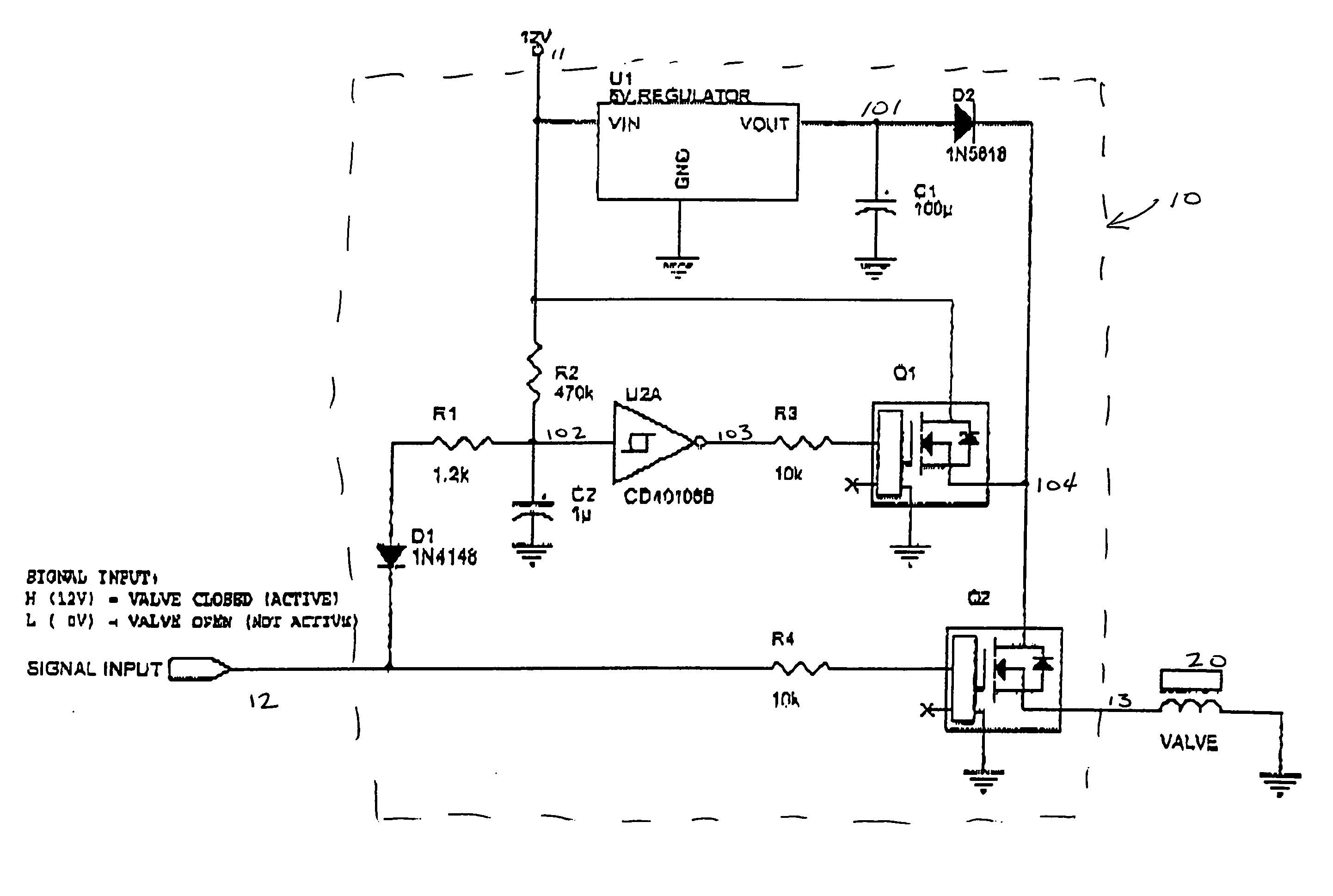
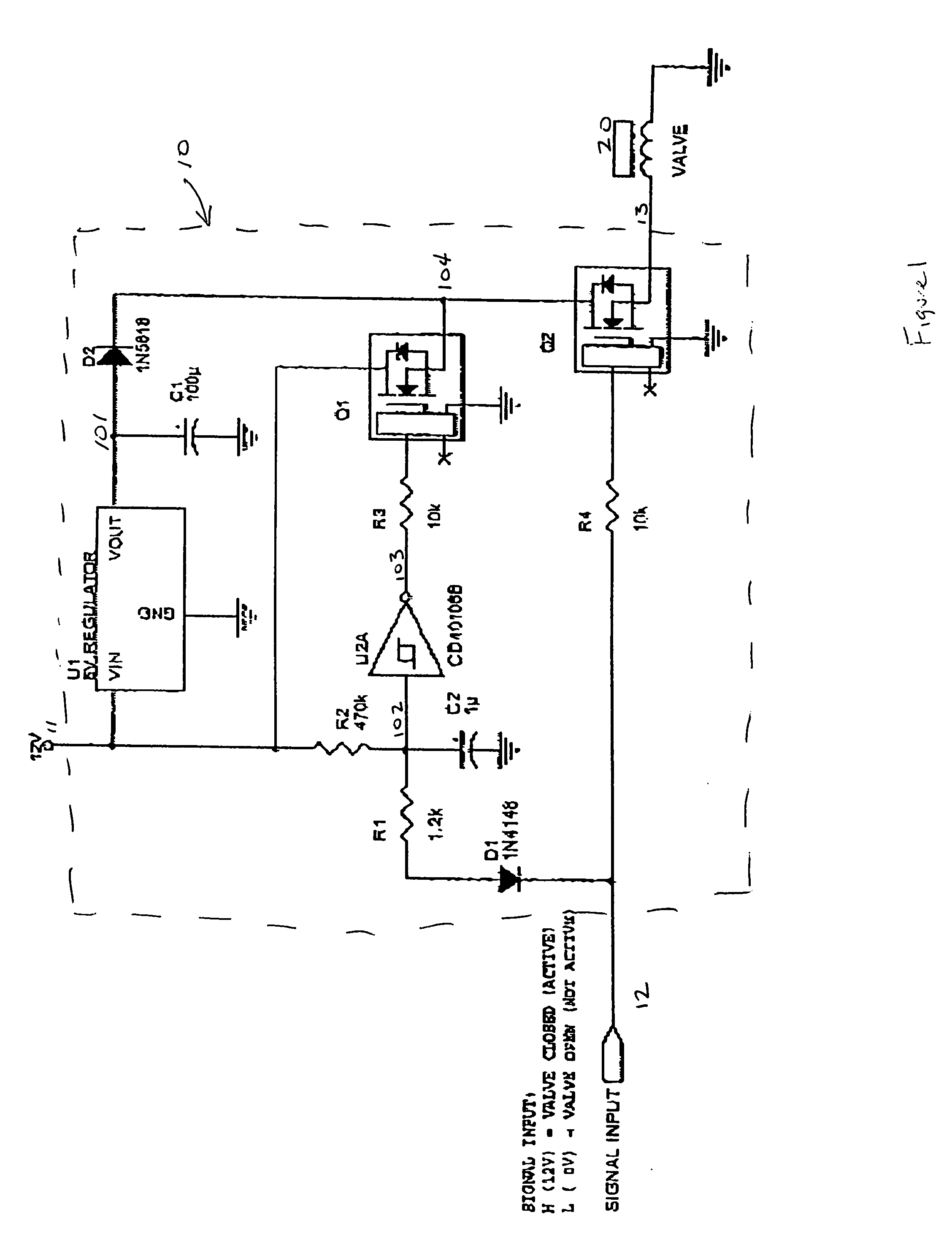
[0017]FIG. 1 is a schematic diagram of the preferred embodiment of the present invention. Variations of this circuit are possible without deviating from the spirit of the invention. The preferred embodiment of the circuit has a power input 11, a signal input 12 and an output signal 13.

[0018] The power input, 11, supplies voltage to the several components in the circuit 10 and to the solenoid 20. Any suitable power source (not shown) can be used to supply the requisite power input to the circuit 10. The amount of voltage supplied also is not particularly limited, and can include 24, 12 and 5 volts and is preferably 12 volts.

[0019] The circuit has a single input signal 12 that is used to enable the solenoid 20. In this embodiment, the circuit 10 allows voltage to be passed to the solenoid 20 via the output signal 13 when the enable signal 12 is a logic high. Alternatively, those skilled in the art will appreciate that the circuit can be designed such that the solenoid 20 is powered ...


PUM

PropertyMeasurementUnit
voltageaaaaaaaaaa
voltageaaaaaaaaaa
voltageaaaaaaaaaa

Abstract

The present invention provides a system and method for controlling a solenoid that ensures accurate timing between the enabling of the driving circuit and the activation of the solenoid, while simultaneously providing a two energy level driving scheme to reduce power consumption. The present invention utilizes a single enable signal and supplies the solenoid two different energy levels, a higher “set” level and a lower “hold” level. The generation of these two levels is based on the enabling signal and guarantees that the higher “set” level is present when the solenoid is activated, thereby minimizing undesirable timing jitter.

Description

BACKGROUND OF THE INVENTION [0001] Solenoids are widely used to convert electrical energy into mechanical movement and, due to their utility, are used in a wide range of applications, from time-critical valves to power locks in automobiles to simple doorbells. [0002] Briefly, a solenoid consists of an electrical wire, typically circularly wrapped to create a coil. A magnetically conductive rod is placed inside the coil. When current passes through the coil, a magnetic field is created, which causes the rod to move relative to the coil. In numerous embodiments, a biasing member such as a spring is used to return the rod to its inactive state when the current ceases to flow through the coil. [0003] A simple example of a solenoid is the traditional doorbell. When the user actuates the doorbell, that action connects the coiled wire to the power source, thereby creating a magnetic field within the coiled wire. This field causes a magnetically conductive plunger to move and typically stri...

Claims


Application Information

Patent Timeline
Patent Type & Authority Applications(United States)
IPC IPC(8): H01F7/18H02P25/06H03K17/041
CPCH03K17/04106
Inventor JOENS, MICHAEL
Owner MILLIPORE CORP
Why Eureka
Try Eureka