Fuel cell with pre-shaped current collectors

a current collector and fuel cell technology, applied in the field of fuel cells, can solve the problems of limited cathodic generation of water, and limited use of reformer based systems presently to comparatively large amounts

Inactive Publication Date: 2005-11-10
MTI MICROFUEL CELLS
View PDF9 Cites 15 Cited by
  • Summary
  • Abstract
  • Description
  • Claims
  • Application Information

AI Technical Summary

Benefits of technology

[0021] In another embodiment of the present invention, a substantially flat compression plate may be used to compress the pre-shaped current collectors. The pre-shaped current collectors may maintain their original curvature during compression, alleviating the need for a curved compression plate.

Problems solved by technology

However, because fuel processing is complex, and requires expensive components, which occupy comparatively significant volume, the use of reformer based systems is presently limited to comparatively large, high power applications.
The overall reaction may be limited by the failure of either of these reactions to proceed at an acceptable rate (more specifically, slow oxidation of the fuel mixture will limit the cathodic generation of water, and vice versa).
Use of the compliance layer, however, adds another manufacturing material to the layers of the fuel cell assembly, and in some situations, may not adequately prevent the assembly from bending outwards.

Method used


Image

  • Fuel cell with pre-shaped current collectors
  • Fuel cell with pre-shaped current collectors
  • Fuel cell with pre-shaped current collectors

Examples


Embodiment Construction

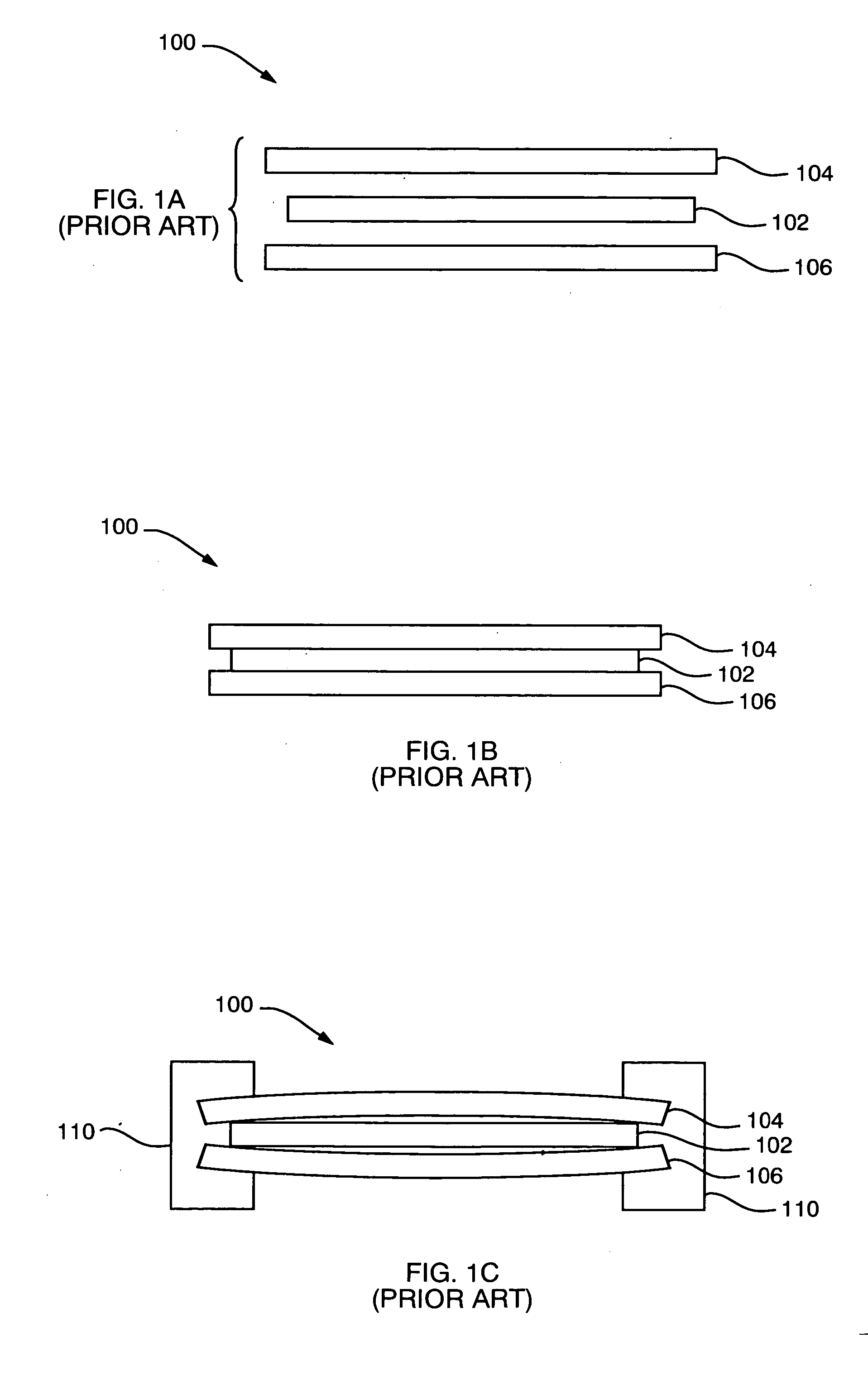
[0041] By way of background, FIG. 1A shows a cross section of a basic (prior art) fuel cell 100 prior to a compressed state. A membrane electrode assembly (MEA) 102 is shown between a cathode current collector 104 and an anode current collector 106. Details regarding fuel cell operation can be found in commonly-owned U.S. patent application Ser. No.: 10 / 413,983, filed on Apr. 15, 2003 by Ren et al. for a DIRECT OXIDATION FUEL CELL WITH PASSIVE WATER MANAGEMENT, which is herein incorporated by reference. Those skilled in the art will recognize that the invention set forth herein can be used with MEAs employing architectures other than those described in the above-mentioned application Ser. No. 10 / 413,983.

[0042] Referring now to FIG. 1B, the cross section of the fuel cell 100 is shown in a compressed state prior to molding. During this state, the multi-layer assembly 100 is in pure compression. The total stiffness k of the assembly 100 is given by the following equation: 1k=1kA+1kME...


PUM

PropertyMeasurementUnit
contact resistanceaaaaaaaaaa
conductiveaaaaaaaaaa
shapeaaaaaaaaaa

Abstract

The present invention discloses a process for manufacturing a fuel cell and an associated fuel cell array that includes novel pre-shaped current collectors and conforming compression plates. The current collectors are pre-shaped to counteract any deflection of the fuel cell after compression is released during manufacture. The pre-shaped current collectors may bend outwards by the same amount as previously, however, the overall compression relaxation may be much lower because the pre-shaped current collectors are bending back into the flat position, as opposed to away from it. Also provided with the present invention are associated mold plates that induce the desired pre-shaping to the current collectors.

Description

BACKGROUND OF THE INVENTION [0001] 1. Field of the Invention [0002] This invention relates generally to fuel cells, and more particularly, to the manufacture of such fuel cells. [0003] 2. Background Information [0004] Fuel cells are devices in which electrochemical reactions are used to generate electricity. A variety of materials may be suited for use as a fuel depending upon the nature of the fuel cell. Organic materials, such as methanol or natural gas, are attractive fuel choices due to their high specific energy. [0005] Fuel cell systems may be divided into “reformer-based” systems (i.e., those in which the fuel is processed in some fashion to extract hydrogen from the fuel before it is introduced into the fuel cell) or “direct oxidation” systems in which the fuel is fed directly into the cell without the need for separate internal or external processing. Most is currently available fuel cells are reformer-based fuel cell systems. However, because fuel processing is complex, an...

Claims


Application Information

Patent Timeline
Patent Type & Authority Applications(United States)
IPC IPC(8): H01M8/02
CPCH01M8/0232H01M8/0245Y02E60/50H01M8/0273H01M8/1011H01M8/0247Y02P70/50
Inventor MINAS, CONSTANTINOSHIRSCH, ROBERT S.
Owner MTI MICROFUEL CELLS
Why Eureka
Try Eureka