

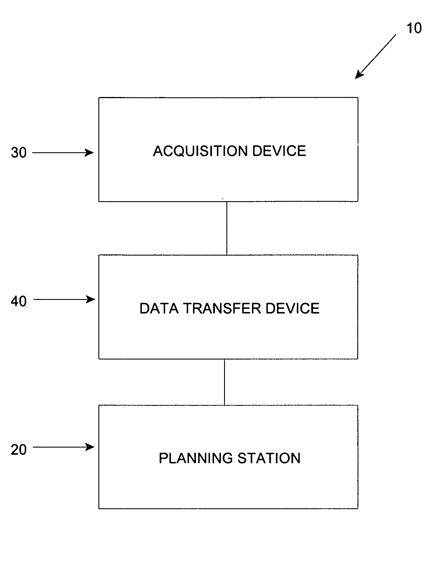
Planning method and planning device for knee implants
a planning method and technology for knee implants, applied in the field of knee implants planning methods and devices, can solve the problems of insufficient realistic simulation, point-by-point tracking or motion capture for individual points, and low yield of relative movement and contact information
- Summary
- Abstract
- Description
- Claims
- Application Information
AI Technical Summary
Benefits of technology
Problems solved by technology
Method used
Image

Examples
Embodiment Construction
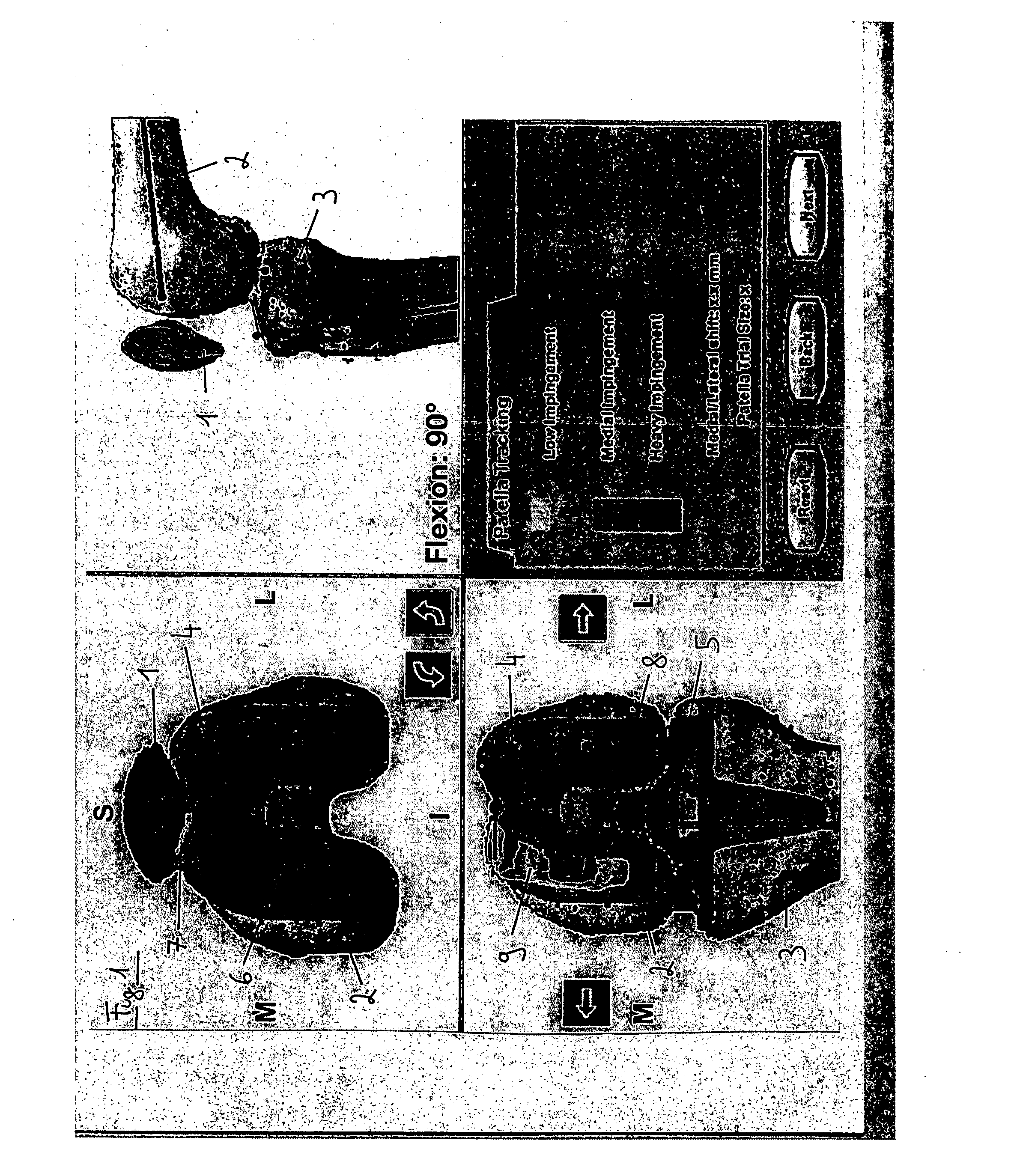
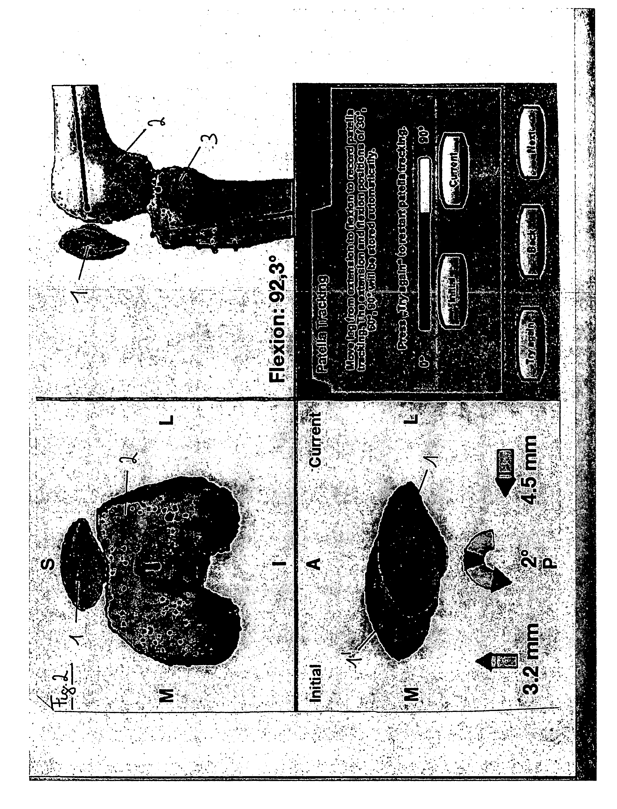
[0020] Advantages of the present invention are based on the fact that the patient's genicular anatomy is detected spatially and / or according to its surface contour, such that contact and impingement between the implant and the parts of the genicular anatomy can be detected and simulated far more extensively and with a far higher yield of information. On the basis of these results, a possible problem in a currently proposed implant positioning can then be identified far more precisely than previously, and the positioning can be adjusted until the problem no longer arises.
[0021] In other words, the invention is also a part of the patella tracking function of a surgical, computer-assisted planning system. The general idea is also to track the movement of the patella towards the femur, wherein as a post-operative result, the patella or a patella implant should slide on the femur or femur implant in such a way that the patient does not feel any pain at the rear or front part of the pate...
PUM
 Abstract
Description
Claims
Application Information