Magnetic vector control system

a control system and magnetic field technology, applied in the field of magnetic field control system, can solve the problems of improper biomechanics, osteoarthritis in joints, dysfunction and pain, etc., and achieve the effect of convenient control and construction

Inactive Publication Date: 2005-11-10
HYDE EDWARD ROBERT JR
View PDF3 Cites 61 Cited by
  • Summary
  • Abstract
  • Description
  • Claims
  • Application Information

AI Technical Summary

Benefits of technology

[0024] Stabilizing forces for repulsive MVCS to control shears that occur when two simple magnets are placed in repulsion can be accomplished readily by the use of Magnetic Arrays instead of plain magnets on the repulsive side.
[0025] Attractive MVC...

Problems solved by technology

These problems produce maladaptive biomechanics of a joint or an extremity segment and lead to dysfunction and pain.
Osteoarthritis in joints occurs ...

Method used


Image

  • Magnetic vector control system
  • Magnetic vector control system
  • Magnetic vector control system

Examples


Embodiment Construction

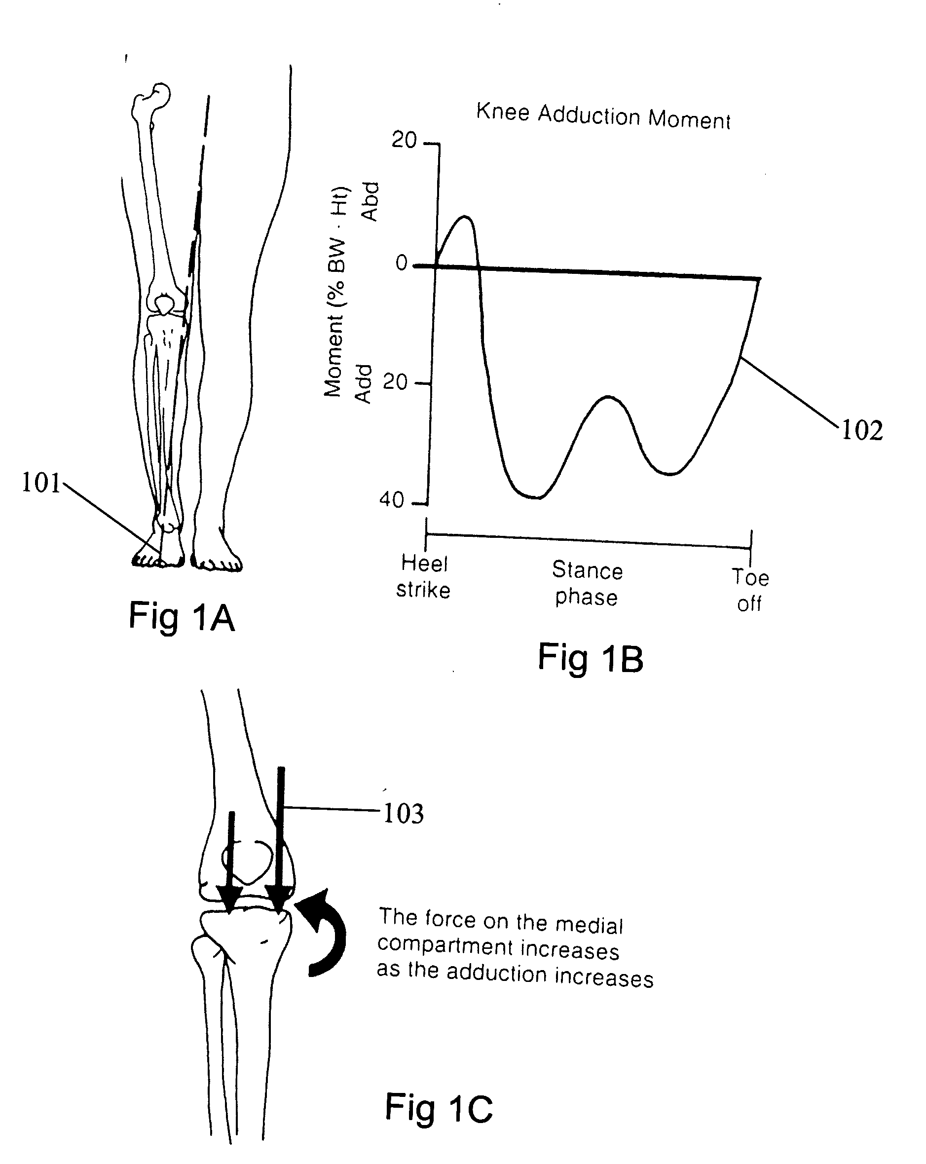
[0049]FIG. 1A shows a drawing depicting a weight bearing axis 101 that corresponds to a double leg stance. FIG. 1B is a representation of the single leg moments 102 in stance phase (weight bearing). These moments change throughout the stance phase from heel strike to toe off. Most of the moments are ADduction moments. These ADduction moments FIG. 1C103 increase the force on the medial compartment.

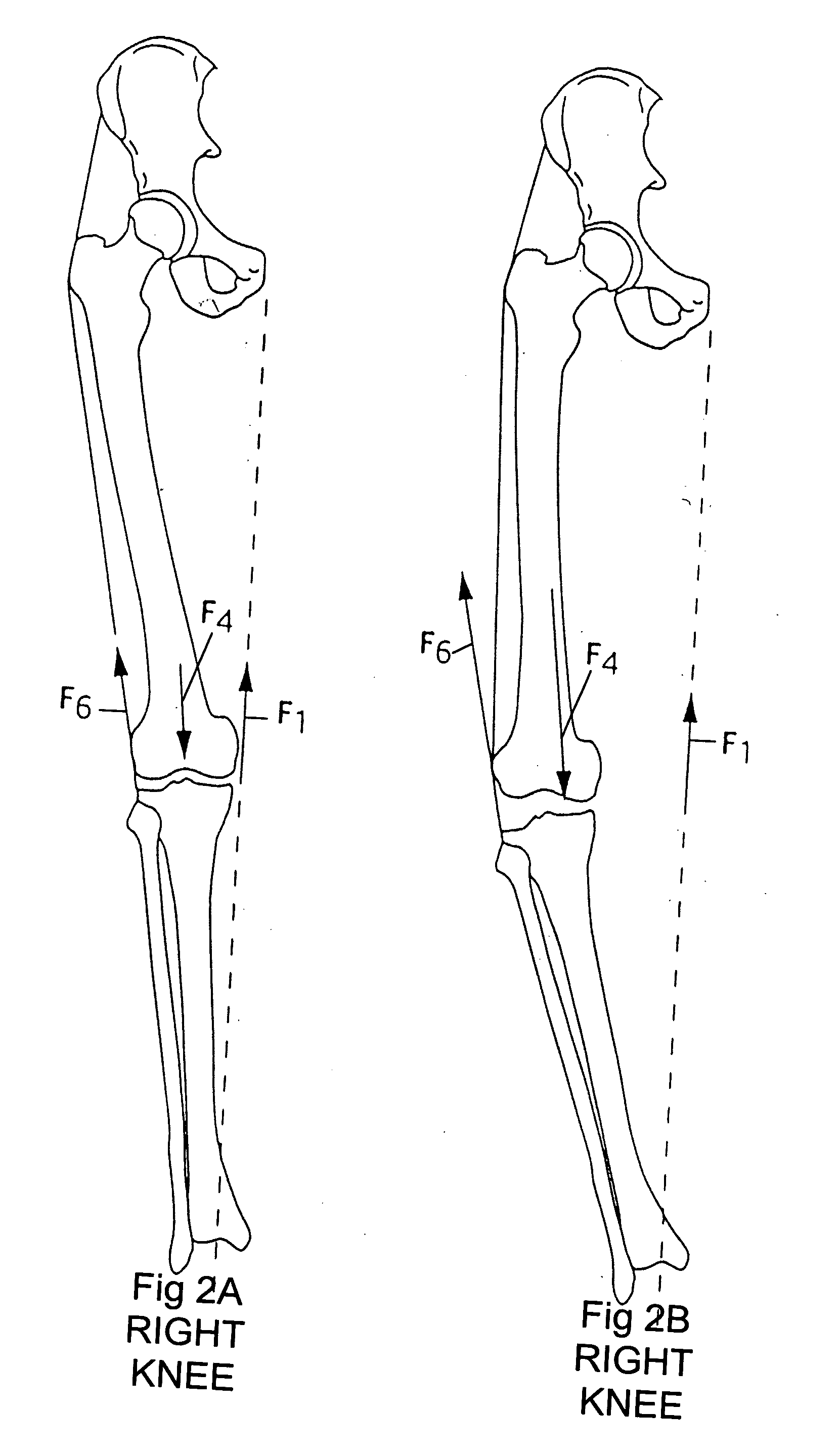
[0050]FIGS. 2A and 2B compares the forces of a normal knee alignment FIG. 2A and a knee in varus alignment FIG. 2B. The Joint Reaction Force ORF) F4 moves further medial in the medial compartment FIG. 2B and larger forces are required to balance the ADduction moment. (F6: Abductor Muscle Force; F4: Joint Reaction Force; F1: Mechanical Axis)

[0051]FIGS. 3A, 3B, 3C show the same forces as in FIG. 2A, 301 and FIG. 28, 302 which are static diagrams. FIG. 3C is a normal knee as in FIG. 3A dynamically loaded. Showing a dynamic ADduction moment 303 during stance

[0052] The dynamically loaded knee...


PUM


Abstract

Aging, injury and/or other pathologies of joints, especially weight bearing joints, contribute to changes in natural biomechanics. Deviations from optimal biomechanics lead to acceleration of the natural history of joint pathology and ultimately osteoarthritis. A Magnetic Vector Control System made up of an assembly of magnetic field sources can be disposed at or near a joint typically on or in adjacent bones of the joint, on one side of a first mechanical axis that creates a torque or moment about a second different axis of the joint, that intersects the first mechanical axis, to decrease the joint reactive force at the joint surface or equivalently substantially shift the first mechanical axis to a new or preferred position.

Description

[0001] This application claims the benefit of provisional application MAGNETIC VECTOR CONTROL SYSTEM—No. 60 / 521,499 that was filed on May 6, 2004.BACKGROUND OF INVENTION [0002] Treatment for joint pathologies usually beings well after symptoms reach substantial levels and the patient is experiencing pain and dysfunction. [0003] Many times underlying pathologies are known prior to the onset of symptoms whether due to injury, congenital problems or acquired problems. These problems produce maladaptive biomechanics of a joint or an extremity segment and lead to dysfunction and pain. Osteoarthritis in joints occurs and is accelerated by improper biomechanics. Currently early treatments concentrate on physical therapy, bracing and assist devices. These treatments are directed towards decreasing symptoms and hopefully slowing the natural progression of the disease. [0004] The improper biomechanics at the joint or segment can stem from structural, mechanical, motor, neurological or metabol...

Claims


Application Information

Patent Timeline
IPC IPC(8): A61F2/00A61F2/38A61F5/00
CPCA61F2/38A61F2/3836A61F2210/009A61F2002/48A61F2002/30079A61F2/48
Inventor HYDE, EDWARD ROBERT JR.
Owner HYDE EDWARD ROBERT JR
Why Eureka
Try Eureka