
Trapezium implant for thumb and method

a technology applied in the field of thumb and implant, can solve the problems of prior art prosthesis slipping out of place, insufficient ligament reconstruction, compounding the pathological process, etc., and achieve the effect of increasing strength and longevity

Inactive Publication Date: 2005-11-10
WRIGHT MEDICAL TECH
View PDF36 Cites 52 Cited by
  • Summary
  • Abstract
  • Description
  • Claims
  • Application Information

AI Technical Summary

Benefits of technology

[0008] It is an object of the invention to provide a trapezium implant of increased strength and longevity.
[0009] It is an object of the invention to provide a trapezium implant that is less likely to become dislodged from its proper positioning.
[0010] It is an object of the invention to provide a trapezium implant that is easy to implant and firmly position.

Problems solved by technology

Undetected articular damage may also accompany such trauma, thereby compounding the pathological process.
For more advanced arthrosis, ligament reconstruction is not sufficient.
In view of the very slippery, low coefficient surface of the material of the prosthesis, and the fact that the elastomeric material of the prosthesis is difficult to handle and will not hold a stitch, when implanted, the prior art prosthesis has a tendency to slip out of place in that the opposite end of the cylindrical portion of the prosthesis merely rests against the adjacent navicular.
Furthermore, when implanted, the amount of force applied by the patient, in a pinching direction of the hand, must be limited in order to prevent inadvertent popping out of the prior art prosthesis.
As is readily apparent, considering the type of material which must be employed for an implantable prosthesis, the tails or extending elements are extremely fragile, and tend to wear and break thereby losing the fixation sought to be obtained.
In addition, it is difficult to firmly secure the elastomeric tails to the hand structure, thereby resulting in the patient having to limit the use of his hand with reference to the application of hand grip forces.

Method used


Image

  • Trapezium implant for thumb and method
  • Trapezium implant for thumb and method
  • Trapezium implant for thumb and method

Examples


Embodiment Construction

[0019] With reference to the figures, an exemplary embodiment of a trapezium prosthesis / implant for the thumb that meets and achieves all the above-mentioned objects of the invention will now be described.

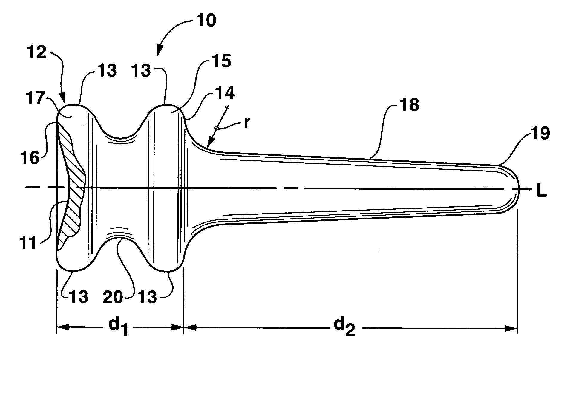
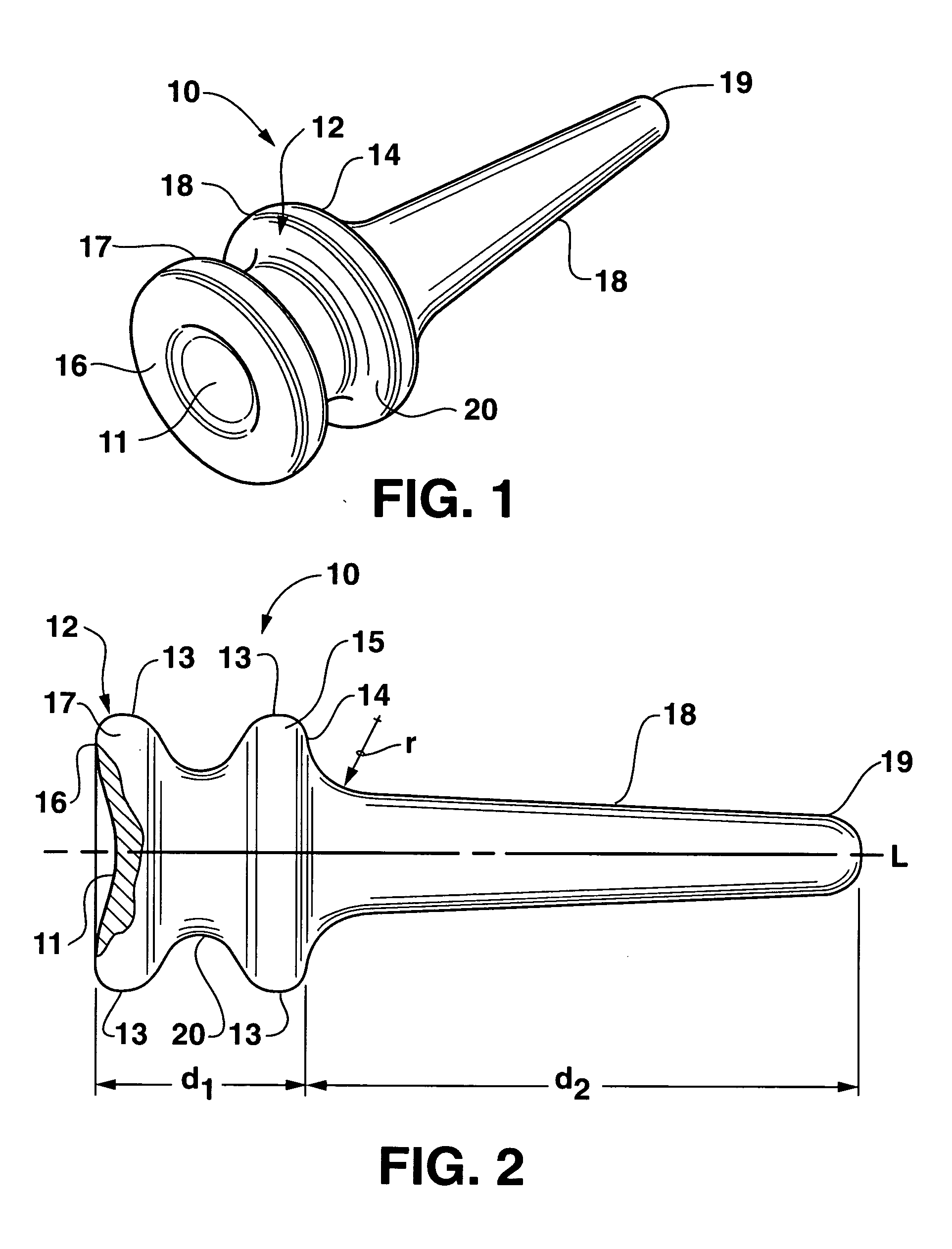
[0020] Referring to FIGS. 1 and 2, the exemplary embodiment of the trapezium implant according to the invention is generally designated by the numeral 10 and comprises an integral elastomeric member, preferably a silastic material such as silicone rubber, and which is inherently flexible and physiologically inert. The implant 10 includes a body portion 12 having tapered conical portions 15 and 17 separated by a tapered neck 20. Tapered portions 15 and 17 have end faces 14 and 16, respectively. Integrally formed and projecting from the end face 14 is an elongated, longitudinally extended tapered portion18 which extends along the longitudinal axis L of implant 10. Tapered portion 18 will have a length d2 that is typically equal to 3 (three) times the length d1 of body portion 12 so ...


PUM


Abstract

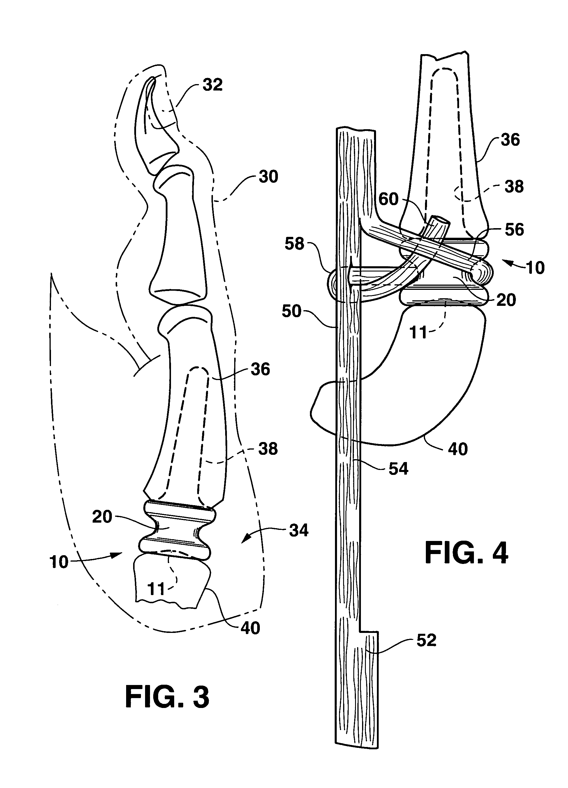
An implant for the trapezium of the thumb carpometacarpal (CMC) joint comprising an integral elastomeric member configured to include a body portion having a tapered neck, having extending from one end thereof an elongated, longitudinally extending tapered portion adapted to be embedded into a reamed out-channel in the thumb metacarpal bone. After implantation, in the preferred embodiment of the method according to the invention, a segment of a nearby tendon, for example, the APL or FCR tendons, may be wrapped around the tapered neck of the implant to secure it in position, thereby forming a reinforced structure to inhibit dislocation of the prosthesis. However, in other methods, various other securing elements, including, but not limited to acellular matrices, may be used to retain the implant in position.

Description

BACKGROUND OF THE INVENTION [0001] Freedom from pain is essential for normal thumb function. Although the carpometacarpal (CMC) joint of the thumb is described as a saddle joint, it is actually formed by apposed saddles, one astride the other, each one's longitudinal axis perpendicular to the other. Such a relationship creates a joint where two primary planes of motion, flexion-extension and adduction-abduction, are perpendicular to one another. With rotary movement such as opposition and circumduction, the surfaces are twisted into a less congruous relationship, causing tightening of the joint capsule and thereby increasing joint stability, provided all ligaments are competent. [0002] Idiopathic hypermobility of the thumb basal joint is not uncommon, particularly in women, and would seem to be a major factor in producing the arthrosis which so frequently afflicts the CMC joint. Trauma, acute or recurrent, causing partial tears or stretching of the ligaments, likewise will produce v...

Claims


Application Information

Patent Timeline
Patent Type & Authority Applications(United States)
IPC IPC(8): A61F2/00A61F2/08A61F2/30A61F2/42
CPCA61F2/08A61F2/0811A61F2/4241A61F2/4261A61F2230/0067A61F2002/30205A61F2002/30822A61F2002/4258A61F2002/4276A61F2002/30069
Inventor CALANDRUCCIO, JAMES H.JOBE, MARK T.PATTERON, CHAD J.
Owner WRIGHT MEDICAL TECH
Learn More