
Snake plunger

a plunger and plunger technology, applied in water installations, cleaning processes and apparatuses, constructions, etc., can solve the problems long time problem of toilet clogging, and overflowing, so as to reduce the cost of consumers, eliminate splashing, and reduce the effect of overflowing waste water

Inactive Publication Date: 2005-11-17
HOFER WILLIAM RICHARD SR +1
View PDF6 Cites 6 Cited by
  • Summary
  • Abstract
  • Description
  • Claims
  • Application Information

AI Technical Summary

Benefits of technology

[0009] Another object of the invention is to eliminate splashing and reduce overflow waste water.
[0010] Another object of the invention is to decrease the cost to the consumer, having it all in one tool.
[0013] Still yet another object of the invention is the length of the stationary handle provides room for a longer snake.
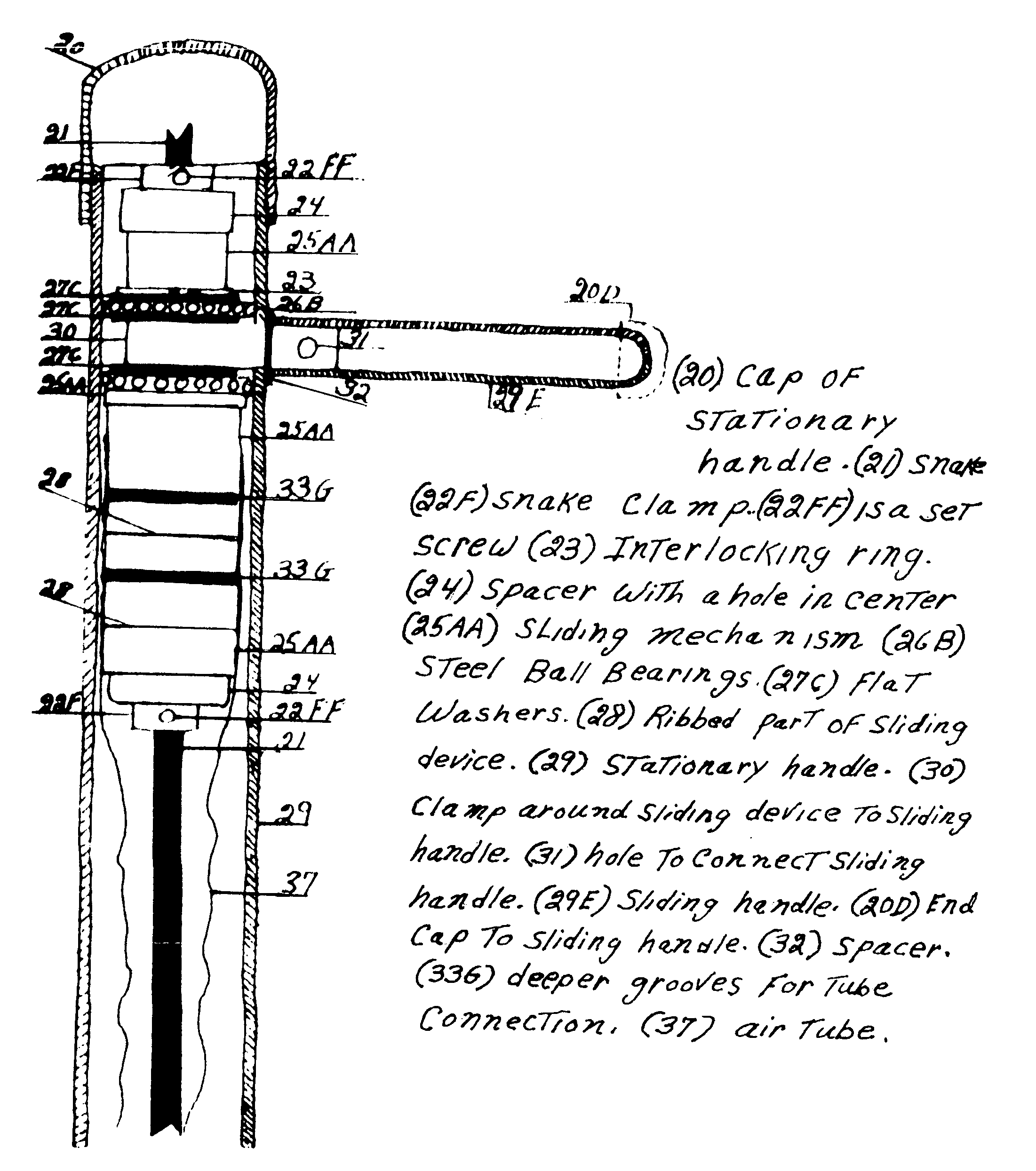
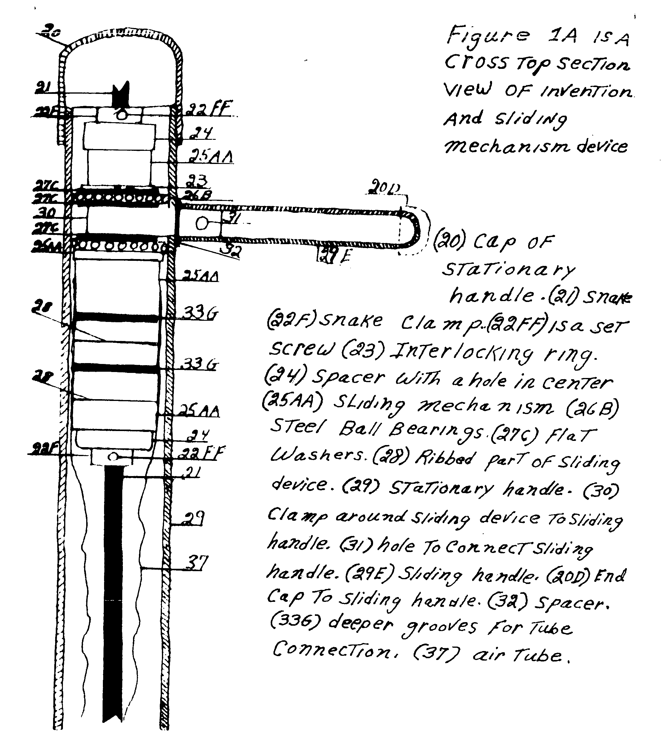
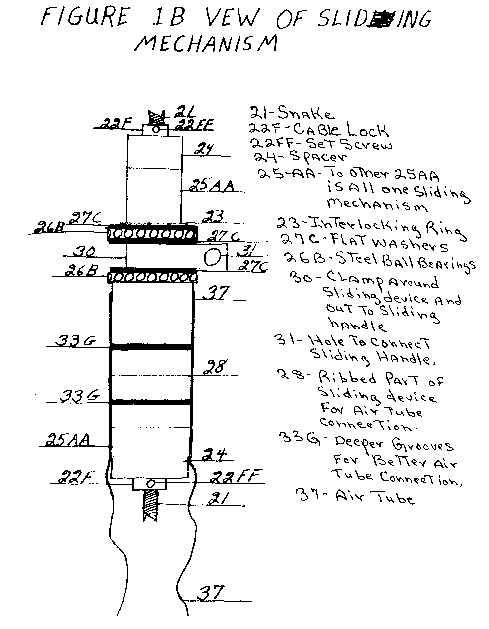
[0015] In accordance with a preferred embodiment of the invention, there is disclosed an apparatus for unclogging a toilet comprising of the sliding mechanism containing steel ball bearings allowing for easier operation. The unique sliding mechanism easily allows movement of the snake within the handle, no other plunger has this sliding mechanism, which makes this plunger unique. The sliding handle is in a locked position when the snake is not in use. The rubber air tube, when plunging, allows very little, if any, water to enter. There is a reducer connecting the plunger to the stationary handle. There is also a flat washer connected to a smaller reducer (also referred to as lower ribbed connection for air tube nipple) which prevents the reducer from sliding up the stationary handle, thus being able to stretch out and hold in place the air tube, which is held in place by the stationary handle. The snake goes through the smaller reducer and up the hollow tube to the sliding mechanism. The top end of the rubber tube is connected to the sliding mechanism. The top end of the snake is threaded through the sliding mechanism, and there is a locking device on the top of the stationary handle connected to the sliding.handle.

Problems solved by technology

The clogging of toilets has been a long time problem, but has become even more of a problem since the use of low-flow toilets which has become mandatory in parts of the United States and will probably be used throughout the United States before long, due to water conservation.
This creates a problem with toilets clogging and over flowing due to insufficient water flow.
First there was the plain plungers that were designed for suction, there was a handle with a rubber suction device on the end, therefore breaking the clog lose.
This was seldom successful.
Then the snake. a twisted wire, which was long and cumbersome.
The plain plunger causes a lot of splashing and spillage, and most often was unsuccessful.
Due to the clogs being deep in the toilet, or drains a person would have to buy a separate snake, which was springy, long and cumbersome and difficult to use.
The short, light plastic, bellowed plunger has a snake embodied within, but the problem with this one is that the snake doesn't go down far enough, in most cases, to unclog the deeper blockage.

Method used


Image

  • Snake plunger
  • Snake plunger
  • Snake plunger

Examples


Embodiment Construction

[0022] Detailed descriptions of the preferred embodiment are provided herein. It is to be understood, however, that the present invention may be embodied in various forms. Therefore, specific details disclosed herein are not to be interpreted as limiting, but rather as a basis for the claims and as a representative basis for teaching one skilled in the art to employ the present invention in virtually any appropriately detailed system, structure or manner.

[0023] Turing first to drawing FIG. 1A, you will notice a cross section view of the top portion of the stationary handle #29, of the apparatus, On the same drawing, there is also a sliding handle #29E, in the locked position. In accordance with an important function of the invention, built inside the handle are the sliding mechanism #25AA, and the snake #21, are also shown. You will notice the air tube #37, that is connected to the sliding mechanism #25AA. The same drawing shows the snake #21 threaded within the sliding device #25A...


PUM


Abstract

An apparatus for unclogging a toilet with the sliding mechanism allowing for easier operation. The sliding mechanism easily allows movement of the snake within the handle. The sliding handle is in a locked position when the snake is not in use. The rubber air tube, when plunging, does not allow water to enter. There is a reducer connecting the plunger to the stationary handle. There is a hollow nipple inside the reducer which connects to the lower end of the rubber tube. The snake goes through the nipple and up the hollow tube to the sliding mechanism. The top end of the rubber tube is connected to the sliding mechanism. The top end of the snake is threaded through the sliding mechanism, and there is a locking device on the top of the sliding mechanism connected to the snake. This is helpful for new “low flow” toilets.

Description

CROSS REFERENCE TO RELATED APPLICATIONS [0001] Not Applicable STATEMENT REGARDING FEDERALLY SPONSORED RESEARCH OR DEVELOPMENT [0002] Not Applicable DESCRIPTION OF ATTACHED APPENDIX [0003] Not Applicable BACKGROUND OF THE INVENTION [0004] This invention relates generally to the field of plumbing, pipes and blockages, and more specifically to the field of blocked, clogged toilets. [0005] The clogging of toilets has been a long time problem, but has become even more of a problem since the use of low-flow toilets which has become mandatory in parts of the United States and will probably be used throughout the United States before long, due to water conservation. This creates a problem with toilets clogging and over flowing due to insufficient water flow. At this time an implement is needed to alleviate the expensive problem of purchasing different types of tools, now available, when one tool would be all that is necessary to the unclogging of toilets. This invention solves this problem....

Claims


Application Information

Patent Timeline
IPC IPC(8): B08B9/04E03C1/302
CPCE03C1/302B08B9/0436
Inventor HOFER, WILLIAM RICHARD SR.HOFER, SHARON LEE
Owner HOFER WILLIAM RICHARD SR
Learn More