Ultrasonic washing apparatus

a washing machine and ultrasonic technology, applied in the direction of other washing machines, cleaning using liquids, textiles and paper, etc., can solve the problem that light weight is no longer an essential factor, and achieve the effect of widening the application of the washing machin

Inactive Publication Date: 2005-11-17
SHARP KK
View PDF4 Cites 9 Cited by
  • Summary
  • Abstract
  • Description
  • Claims
  • Application Information

AI Technical Summary

Benefits of technology

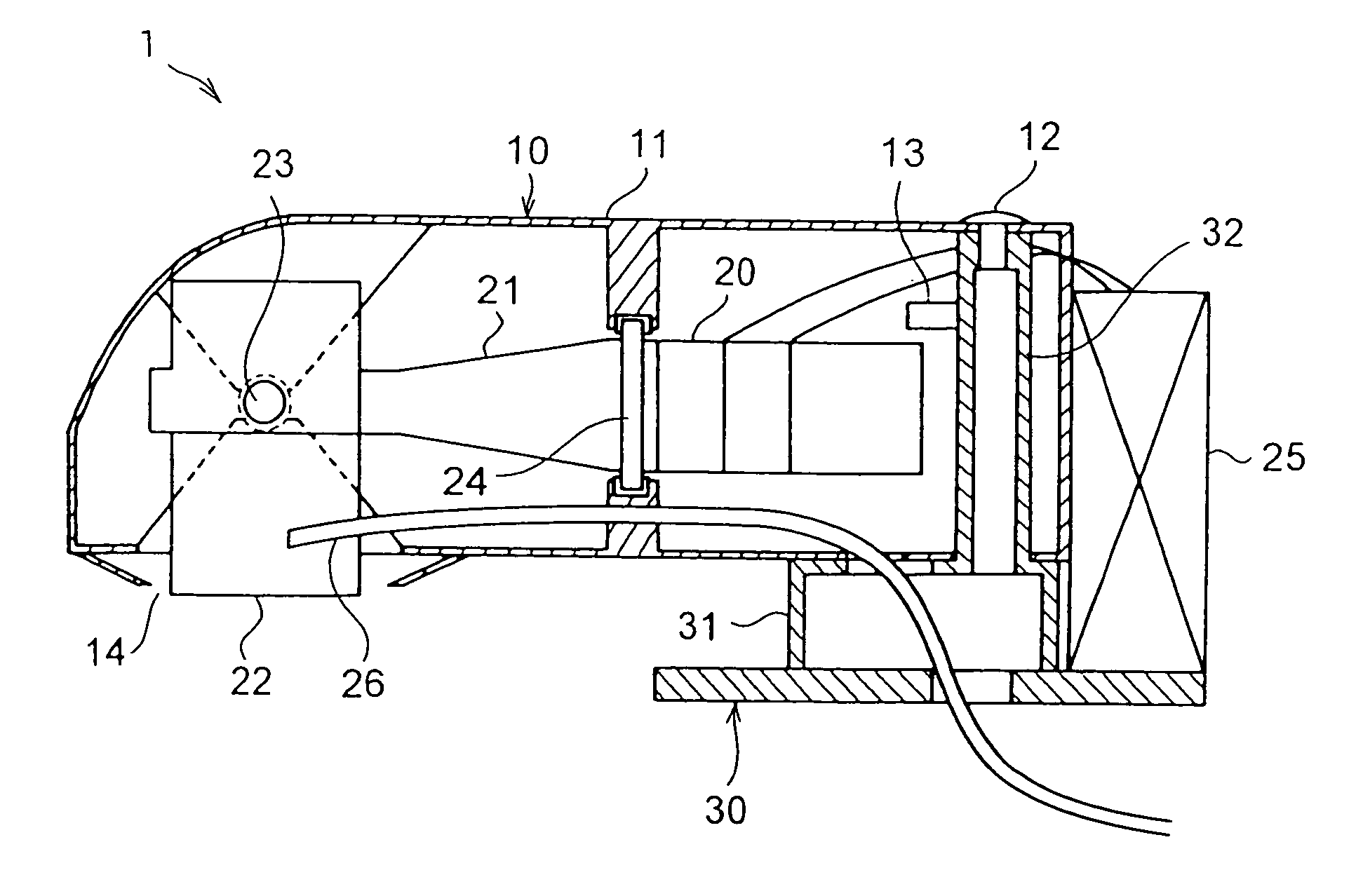
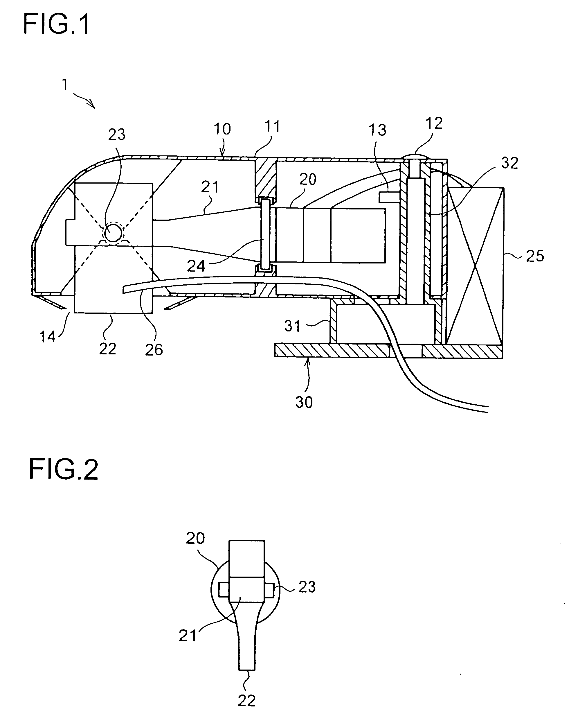
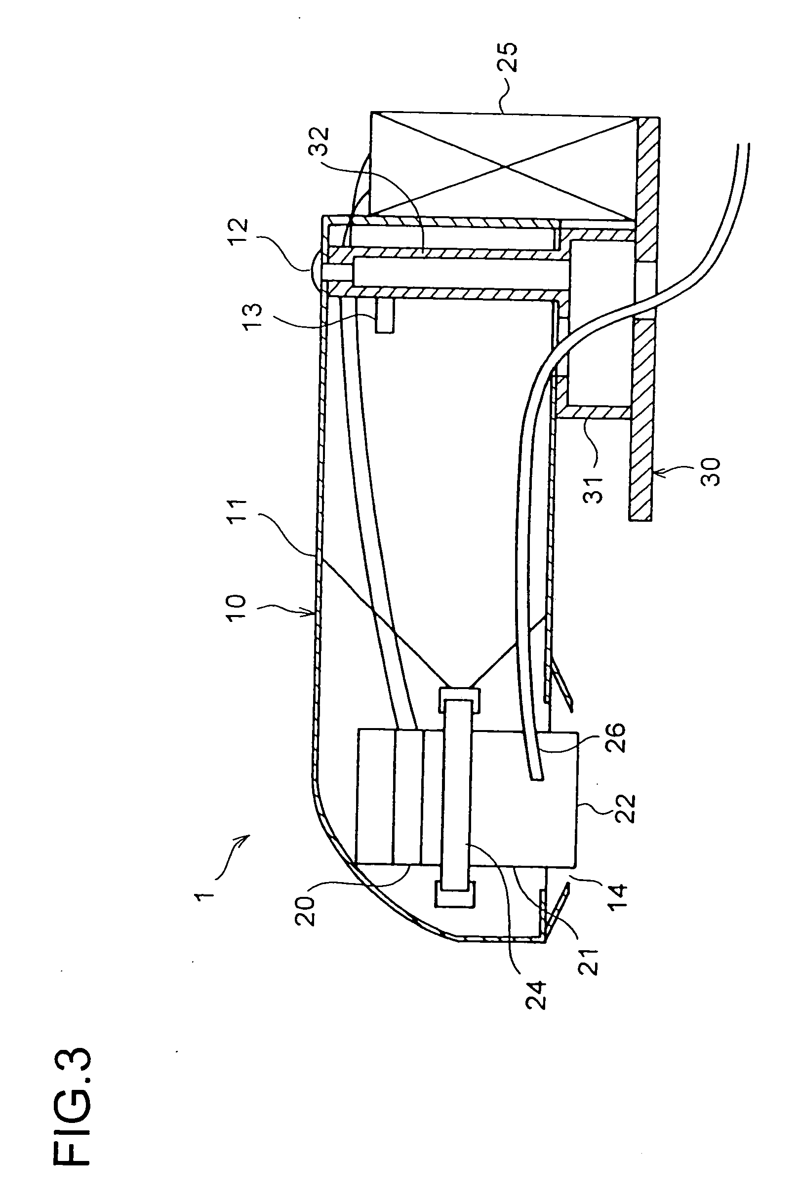
[0018] According to the present invention, the main unit is removable from the fitter. With this construction, whenever necessary, the main unit can be removed from the fitter so that the user can perform washing while holding it with the hand. This makes it possible to freely set the relative position between the washing apparatus and the article to be cleaned, and thus helps further widen the application of the washing apparatus.
[0019] According to the present invention, in the ultrasonic washing apparatus as described above, there is provided a water receiving portion for feeding water simultaneously to the liquid feeder and elsewhere. With this construction, in a case where there is another appliance or a place that requires water, it is possible to operate the ultrasonic washing apparatus while feeding water also to that appliance or place. This makes it possible to share a single faucet, for example, with a washing machine.
[0020] According to the present invention, in the ultrasonic washing apparatus as described above, the main unit is combined with a tray for collecting the liquid fed by the liquid feeder. With this construction, the liquid used in washing can be collected in the tray for disposal. This makes it possible to use the ultrasonic washing apparatus even at a place where the liquid cannot be discharged on the spot.

Problems solved by technology

Thus, lightweightedness is no longer an essential factor.

Method used


Image

  • Ultrasonic washing apparatus
  • Ultrasonic washing apparatus
  • Ultrasonic washing apparatus

Examples


first embodiment

[0046]FIG. 5 shows, in a perspective view, the ultrasonic washing apparatus 1 of the invention. In this embodiment, the fitter 30 has an fitting portion 33 with a C-shaped sectional shape. The fitting portion 33 is so designed as to mount snugly on the rim of a kitchen sink 50. Simply mounting the fitting portion 33 on the rim of the sink 50 permits the ultrasonic washing apparatus 1 to be fitted in position. The fitting portion 33 may be provided with a screw so that it can be fixed by being tightened with the screw. The fitting portion 33 may be fixed more firmly by being bonded with glue or adhesive tape.

second embodiment

[0047]FIG. 6 shows, in a perspective view, the ultrasonic washing apparatus 1 of the invention. In this embodiment, the fitter 30 has an fitting portion 34 shaped like a flat plate. A sticker 35 is provided on the bottom face of the fitting portion 34. The sticker 35 is realized with a permanent magnet. Thus, the magnetic attractive force of the sticker 35 permits the fitter 30 to be fitted to a target object so long as it is made of a magnetic metal such as iron.

[0048] In a case where the sticker 35 is realized with a permanent magnet, the bottom face of the fitting portion 34 may be entirely covered with a single large piece of magnet, or may be strewn with a plurality of small pieces of magnet.

[0049] Advisably, the permanent magnet is so arranged that its height relative to the fitting portion 34 is variable so that, through operation of a lever or the like, the permanent magnet can be moved closer to or away from the target object. With this arrangement, when the permanent magn...

third embodiment

[0052]FIG. 7 shows, in a perspective view, the ultrasonic washing apparatus 1 of the invention. In this embodiment, the fitter 30 includes a bar-shaped or plate-shaped support arm 36. There may be provided one or more of the support arm 36. The support arm 36 is made so long as to cover the width of full-automatic and two-tub washing machines available on the market.

[0053] The support arm 36 is composed of two parallel arm portions coupled together, and is so structured that it can be telescopically displaced. Specifically, in each arm portion, an inner arm 38 is slidably placed inside an outer arm 37. A lock screw 39 for pressing the front-side inner arm 38 is screwed into the front-side outer arm 37 so that, by tightening the lock screw 39, the telescopic displacement of the support arm 36 can be locked at a desired length. Here, “a desired length” denotes any length within the stroke of the displacement of the support arm 36.

[0054] At the ends of the outer and inner arms 37 and ...


PUM


Abstract

An ultrasonic washing apparatus, comprising a body part, an ultrasonic vibrating horn exposed to the outside of the body part, a liquid feeding means for feeding liquid to the ultrasonic vibrating horn, and a mounting means for mounting the body part at any position, the mounting means further comprising a support arm to be installed on an installed object such as a full automatic washing machine, wherein the support arm is extendable, energized in a retracting direction by a helical tension spring, and can stop an extension at any length with a fixing screw, and the body part can change an attitude or a position relative to the mounting means.

Description

TECHNICAL FIELD [0001] The present invention relates to an ultrasonic washing apparatus that permits partial washing of textile articles. BACKGROUND ART [0002] There have conventionally been proposed many apparatuses that achieve washing by exploiting ultrasonic waves. Japanese Patent Applications Laid-Open Nos. 2001-310094 and 2001-310165 disclose handy ultrasonic washing apparatuses. These apparatuses have an ultrasonic horn joined to an ultrasonic vibrator housed in a hand-held casing, and achieve washing with the tip of the ultrasonic horn kept in contact with an article to be cleaned that has been soaked in washing liquid so as to be imbued therewith. The power source is a battery housed in the casing. [0003] These conventional ultrasonic washing apparatuses boast their compactness and light weight, and accordingly produce a rather low output of ultrasonic vibration. Thus, to obtain a satisfactory washing effect, they need to be passed over and over across the article to be cle...

Claims


Application Information

Patent Timeline
Patent Type & Authority Applications(United States)
IPC IPC(8): D06F7/04B08B3/12D06F5/04D06F19/00D06F35/00
CPCB08B3/12D06F35/00D06F19/00D06F5/04D06F7/04
Inventor OOE, HIROKAZU
Owner SHARP KK
Why Eureka
Try Eureka