Integrated circuit with multiple power domains

a technology of integrated circuits and power domains, applied in the direction of pulse techniques, process and machine control, instruments, etc., can solve the problems of significant power consumption in a circuit, leakage current still tends to flow through the sleep transistor, etc., to reduce leakage current, minimize leakage current, and save power

Active Publication Date: 2005-11-17
AVAGO TECH INT SALES PTE LTD
View PDF5 Cites 38 Cited by
  • Summary
  • Abstract
  • Description
  • Claims
  • Application Information

AI Technical Summary

Benefits of technology

[0005] Briefly described, the invention is an integrated circuit having two or more power domains that include load circuits in different portions of the integrated circuit. In order to conserve power, the circuits in one of the power domains are shut down by disconnecting the power source serving that domain. In addition, in accordance with the invention, the load circuits in each power domain are buffered from the load circuits in other power domains by buffer cells. The buffer cells reduce leakage currents in the power domain that is shut down, by restricting data signals from a “live” power domain from reaching the shut-down power domain, and preferably also by providing predetermined voltage signals to the load circuits in the shut-down power domain that are selected to minimize leakage currents in the inactive load circuits. Preferably, the buffer cells are switches, or more preferably logic gates (e.g., AND, OR, NAND, NOR, XOR), that pass data signals between active power domains but provide constant output signals to a power domain whose power source is disconnected.
[0006] Thus, the invention may broadly be described as a circuit having multiple power consumption modes, comprising: a main power domain located on a first portion of an integrated circuit and having one or more terminals capable of outputting data signals; a first switched power domain located on a second portion of the integrated circuit and having one or more terminals capable of receiving data signals; a first controllable power supply capable of providing a first supply voltage t

Problems solved by technology

In the aggregate, such leakage currents can result in a significant amount of power consumption in a circuit.
Nonetheless, some leakage curr

Method used


Image

  • Integrated circuit with multiple power domains
  • Integrated circuit with multiple power domains
  • Integrated circuit with multiple power domains

Examples


Embodiment Construction

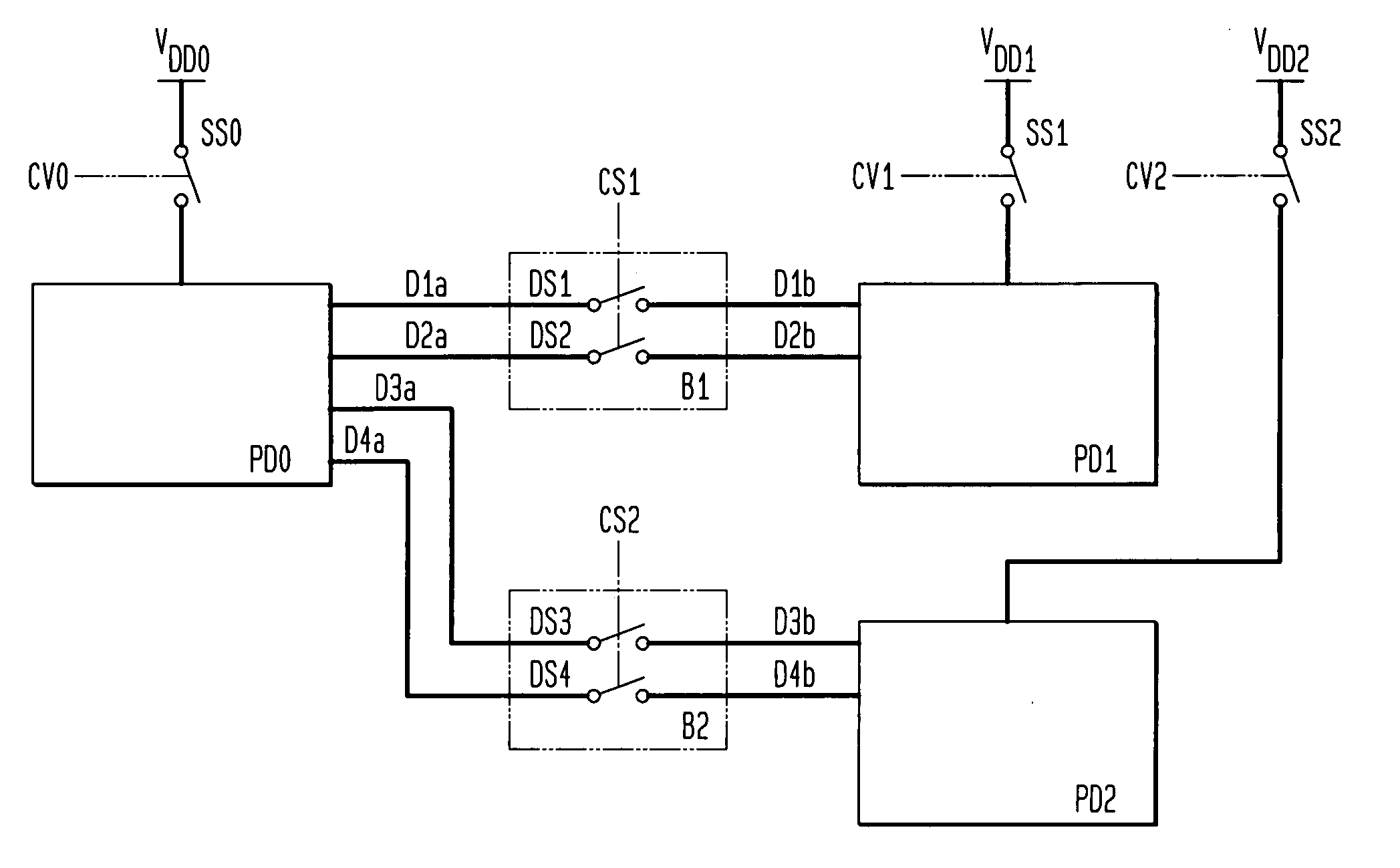
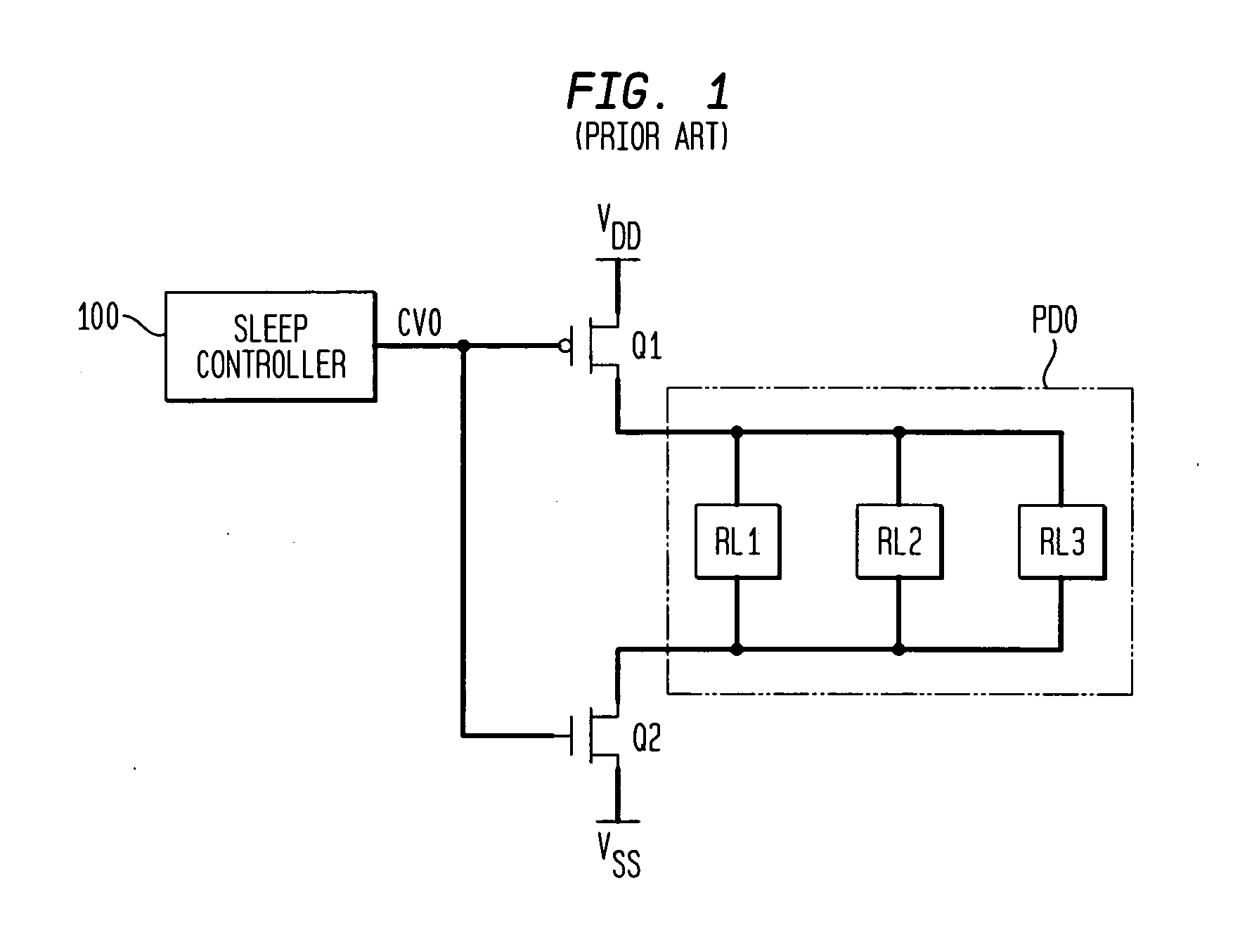
[0011] As described in the Background above, past approaches to power management in integrated circuits have centered around the use of sleep transistors that shut off the power supply for a given load circuit. The present inventors have recognized that even where sleep transistors are used in this fashion, significant leakage currents may still flow in the load circuit as a result of the data signals that may be present at the input terminals of the load circuit. The invention solves this problem by inserting a buffer cell that transparently passes data signals to the load circuit when the power to the circuit is “on” (not disconnected by the sleep transistor) but prevents data signals from reaching the load circuit when the power to the load circuit is “off.”

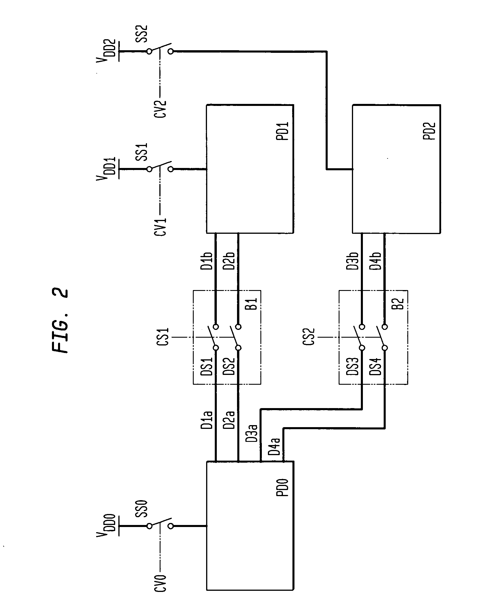
[0012] An integrated circuit in accordance with the present invention is shown in FIG. 2. The circuit comprises two or more power domains PD0, PD1, PD2 that include one or more load circuits (not shown). The load circuits in p...


PUM


Abstract

An integrated circuit having two or more power domains that include load circuits in different portions of the integrated circuit is disclosed. In order to conserve power, the circuits in one of the power domains are shut down by disconnecting the power source serving that domain. The load circuits in each power domain are buffered from the load circuits in other power domains by buffer cells. The buffer cells reduce leakage currents in the power domain that is shut down, by restricting data signals from the “live” power domain from reaching the shut-down power domain, and further by providing predetermined voltage signals to the load circuits in the shut-down power domain that are selected to minimize leakage currents in the inactive load circuits. The invention further provides a corresponding method for reducing power consumption in an integrated circuit having at least two power domains separated by a buffer cell.

Description

CROSS-REFERENCES [0001] This application claims the benefit under 35 U.S.C. § 119(e) of provisional application No. 60 / 542,609 filed Feb. 6, 2004, which is fully incorporated herein by reference.FIELD OF THE INVENTION [0002] The present invention relates generally to power control and reduction of leakage currents in an integrated circuit. BACKGROUND OF THE INVENTION [0003] Ever increasing performance demands are being placed on computer circuits, microprocessors, application specific integrated circuits (ASICs) and other ICs and VLSICs. ASICs, ICs and VLSICs are being required to operate at continually increasing clock speeds to perform more operations in a shorter period of time. To provide these faster operating speeds, circuits and processes are being designed with increasingly smaller geometries and with lower threshold voltages. With these smaller geometries and lower threshold voltages, the flow of leakage current from a system power supply to a circuit supplied by the system...

Claims


Application Information

Patent Timeline
IPC IPC(8): G05F1/10G05F3/02H02J1/00H02J1/14
CPCH02J1/14
Inventor FALKOWSKI, JOHN THOMASLITTLEFIELD, BRUCE GODLEYLOPATA, DOUGLAS D.MECKLAI, HUSSEIN K.REINHOLD, STANLEY
Owner AVAGO TECH INT SALES PTE LTD
Why Eureka
Try Eureka