Apparatus and method for reducing shaft charge

Inactive Publication Date: 2005-11-17
RELIANCE ELECTRIC TECH
View PDF10 Cites 26 Cited by
  • Summary
  • Abstract
  • Description
  • Claims
  • Application Information

AI Technical Summary

Benefits of technology

[0007] According to one embodiment, the present invention comprises a rotatable element, such as a rotor assembly for use with an electric motor. The rotatable element comprises a core having a generally circular cross-section and a channel extending along a centerline of the core, which is generally traverse to the circular cross-section. In the exemplary embodiment, the channel extends from a first end of the core to a second end of the core generally opposite the first end. The rotatable element also includes a shaft that is secured with respect to the core and that extends through the channel such that a portion of the shaft extends beyond at least one of the first and second ends of the core. Additionally, the rotatable element includes a dielectric layer disposed between the shaft and the core to electrically insulate the core and the shaft with respect to one another. Advantageously, the dielectric layer reduces the build-up of charge in the shaft due to parasitic capacitive coupling between the stator and rotor of

Problems solved by technology

Electrostatic coupling, however, results from a number of situations in which rotor or shaft charge accumulation can occur.
For example, ionized or high velocity air passing over a rotor may cause rotor charge accumulation, which, in turn, leads to a build-up of charge on the shaft.
Thus, PWM inverters lead to the development of Vrg levels in the shaft.
Accordingly, the build-up of charge on the inner race of the bearing assembly causes parasitic capacitive coupling with respect to the ball bearings.
Unf

Method used


Image

  • Apparatus and method for reducing shaft charge
  • Apparatus and method for reducing shaft charge
  • Apparatus and method for reducing shaft charge

Examples


Embodiment Construction

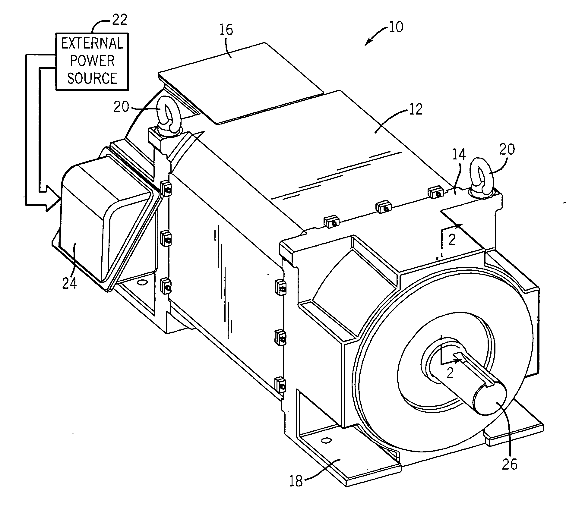
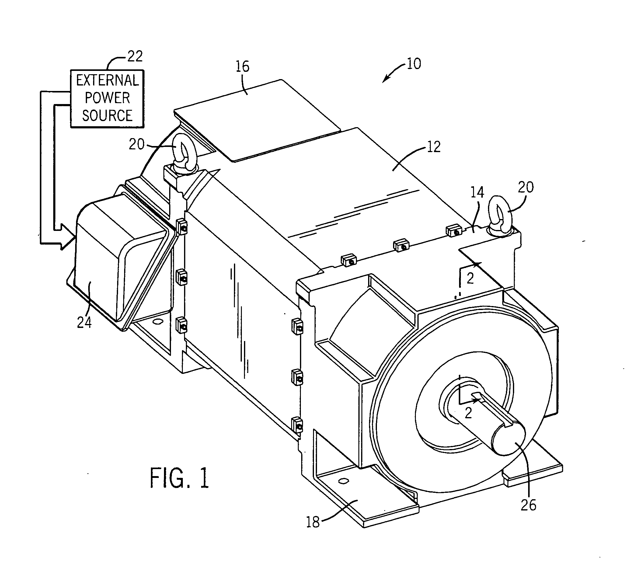
[0015] As discussed in detail below, embodiments of the present invention provide apparatus and methods for reducing the build-up of charge within rotatable members of electromechanical devices. Turning to the drawings, FIG. 1 illustrates an exemplary electric motor 10. In the embodiment illustrated, the motor 10 comprises an induction motor housed in a motor housing. The exemplary motor 10, particularly the motor housing, comprises a frame 12 capped at each end by front and rear endcaps 14 and 16, respectively. The frame 12 and the front and rear endcaps 14 and 16 cooperate to form a protective enclosure or motor housing for the motor 10. The frame 12 and the front and rear endcaps 14 and 16 may be formed of any number of materials, such as steel, aluminum, or any other suitable structural material. Advantageously, the endcaps 14 and 16 may include mounting and transportation features, such as the illustrated mounting flanges 18 and eyehooks 20. Those skilled in the art will apprec...


PUM


Abstract

According to an exemplary embodiment, the present invention provides a rotatable element, such as a rotor for an electric motor. The exemplary rotatable element has a core with a generally circular cross-section and a channel that extends through the core along an axial centerline of the core. The element also includes a shaft that is secured to the core and that is disposed in the channel. Additionally, the element includes a dielectric layer disposed between the shaft and the core that electrically insulates the core and shaft with respect to one another. Accordingly, the dielectric layer prevents current from flowing between the core and the shaft. In turn, the dielectric layer reduces the development of charge in the shaft.

Description

BACKGROUND [0001] The present invention relates generally to electromechanical systems, such as an electric motor. Although the following discussion focuses on electric motors, the present invention affords benefits to a number of electromechanical systems and devices that have rotatable elements. [0002] Electric motors of various types are commonly found in industrial, commercial and consumer settings. In industry, such motors are employed to drive various kinds of machinery, such as pumps, conveyors, compressors, fans and so forth, to mention only a few. Such motors generally include a stator, comprising a multiplicity of coils, surrounding a rotor, which is supported by ball bearings for rotation in the motor housing. When power is applied to the motor, an electromagnetic relationship between the stator and the rotor causes the rotor to rotate. Typically, a rotor shaft extending through the motor housing takes advantage of this produced rotation and translates the rotor's movemen...

Claims


Application Information

Patent Timeline
IPC IPC(8): H02K1/22H02K1/28H02K15/02
CPCH02K1/22H02K15/02H02K1/28
Inventor PIZZICHIL, WILLIAM P.
Owner RELIANCE ELECTRIC TECH
Why Eureka
Try Eureka