Eureka AIR delivers breakthrough ideas for toughest innovation challenges, trusted by R&D personnel around the world.

Apparatus and method for terminating probe apparatus of semiconductor wafer

a technology of semiconductor wafers and probes, applied in the direction of temperature compensation modifications, measurement devices, instruments, etc., can solve the problems of difficult to test the characteristics of semiconductor devices in a wide operating temperature range, and achieve the effects of reducing or minimizing parasitic capacitance, improving test performance and mechanical stability

Inactive Publication Date: 2005-11-17
CELADON SYST
View PDF23 Cites 13 Cited by
  • Summary
  • Abstract
  • Description
  • Claims
  • Application Information

AI Technical Summary

Benefits of technology

"The present invention provides a probe apparatus for testing semiconductor devices that includes a probe and a signal cable connected side by side. The probe has a layer of shielding material made of a center conductive probe needle, a dielectric layer, a conductive guard layer, and a non-conductive sleeve. The signal cable has a center conductor, a dielectric layer, a conductive dispersion / guard layer, and a non-conductive sleeve. The apparatus also includes a chassis or dielectric block for retaining the probe and a tri-axial cable for connecting the probe to the signal cable. The apparatus also includes a shrink tube for shrink-tubing the probe and signal cable together. The apparatus further includes a plate and a cover for improving test performance and mechanical stability. The invention also provides a purge port and a purge tube for providing dry air in the probe apparatus. The technical effects of the invention include improved signal quality, reduced interference, and improved test performance."

Problems solved by technology

As the semiconductor industry grows and devices become more complex, many electrical devices, most commonly semiconductor devices, must be electrically tested, for example, for leakage currents and extremely low operating currents.
Also, because of materials characteristics of dielectrics, it is often difficult to test characteristics of semiconductor devices in a wide operating temperature range.

Method used


Image

  • Apparatus and method for terminating probe apparatus of semiconductor wafer
  • Apparatus and method for terminating probe apparatus of semiconductor wafer
  • Apparatus and method for terminating probe apparatus of semiconductor wafer

Examples


Embodiment Construction

[0022] In the following description of a preferred embodiment, reference is made to the accompanying drawings, which form a part hereof, and in which is shown by way of illustration a specific embodiment in which the invention may be practiced. It is to be understood that other embodiments may be utilized and structural changes may be made without departing from the scope of the present invention.

[0023] For purposes of explanation, numerous specific details are set forth in the following description in order to provide a thorough understanding of the present invention. However, it will be evident to one of ordinary skill in the art that the present invention may be practiced without some of these specific details.

[0024] While this invention is susceptible of embodiment in many different forms, there is shown in the drawings and will herein be described in detailed preferred embodiment of the invention with the understanding that the present disclosure is to be considered as an exe...


PUM


Abstract

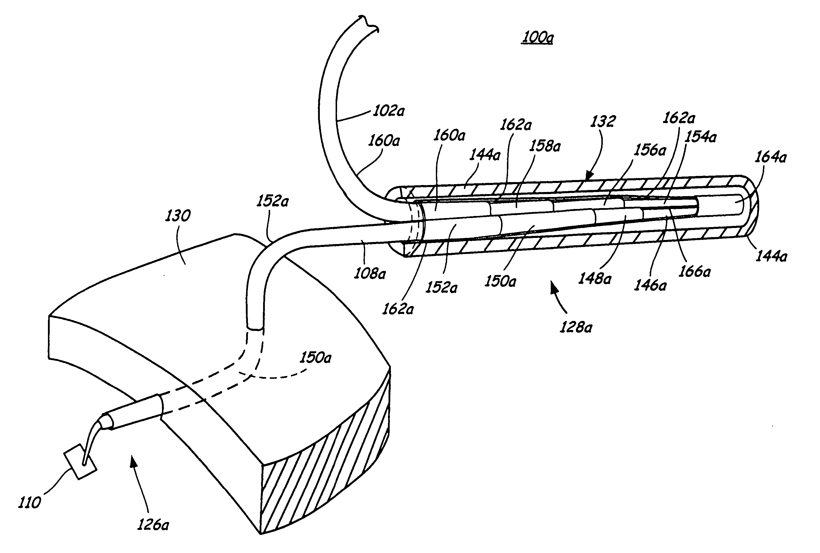
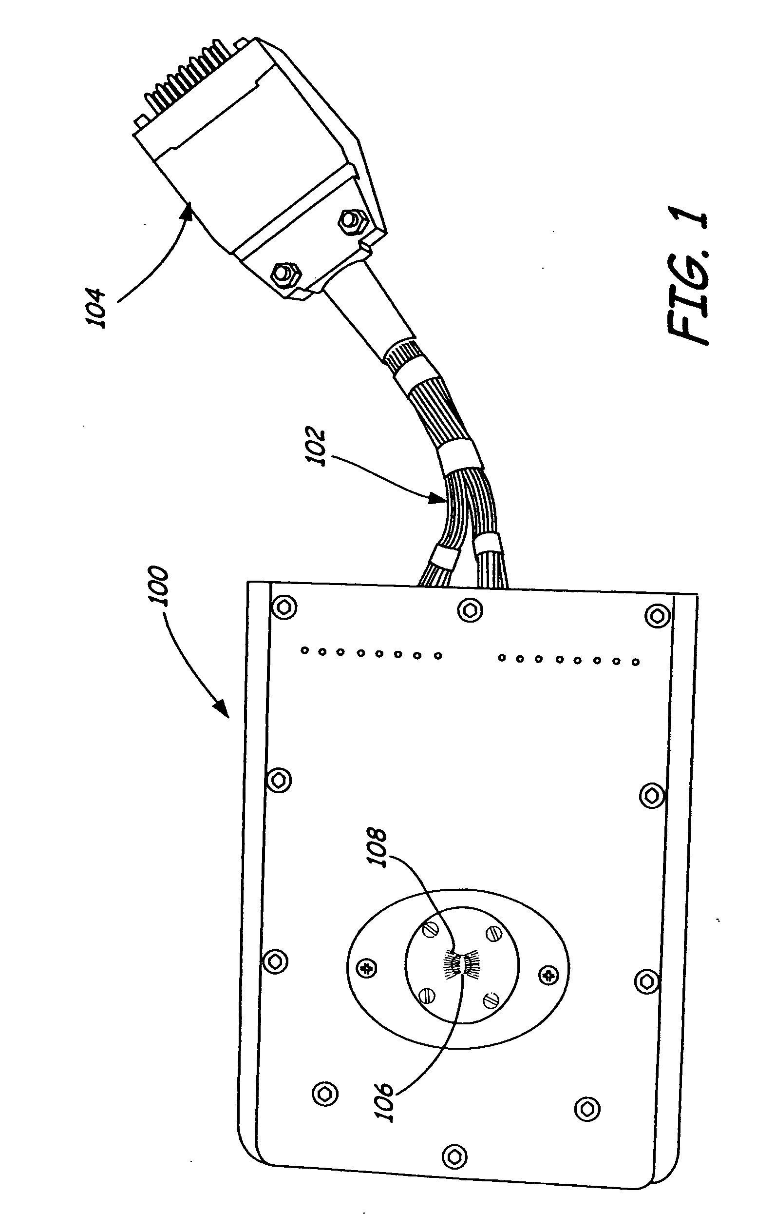
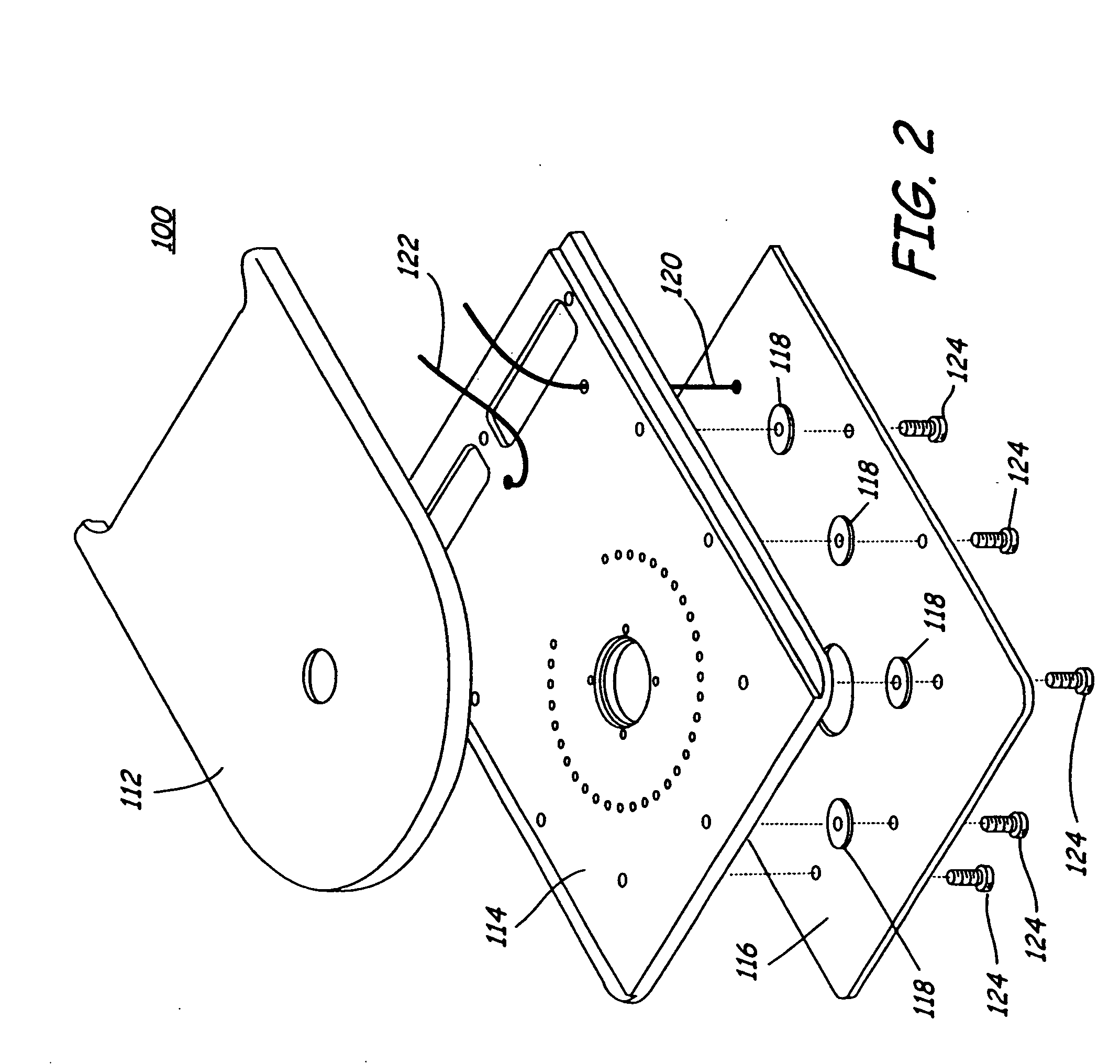
A method and apparatus for terminating a probe that probes a semiconductor device with a signal cable from a tester is provided to connect layers of the probe to layers of the signal cable side by side. The probe and signal cable can be a co-axial or tri-axial probe and signal cable, respectively. A center conductive probe needle of the probe is disposed side by side with and electrically connects to a center signal conductor of the signal cable. A dielectric layer of the probe is disposed side by side with and connects to a dielectric layer of the signal cable. A conductive guard layer of the probe is disposed side by side with and electrically connects to a conductive dispersion / guard layer of the signal cable, and a sleeve of the probe is disposed side by side with and connects to a sleeve of the signal cable. In a tri-axial embodiment, a second dielectric layer of the probe is disposed side by side with and connects to a second dielectric layer of the signal cable.

Description

CROSS-REFERENCE TO RELATED APPLICATION [0001] None. FIELD OF THE INVENTION [0002] The present invention relates generally to semiconductor test equipment, and more particularly, to a probe apparatus used in semiconductor test equipment for electrically probing devices on a semiconductor wafer. BACKGROUND OF THE INVENTION [0003] The semiconductor industry has a need to access many electronic devices on a semiconductor wafer. As the semiconductor industry grows and devices become more complex, many electrical devices, most commonly semiconductor devices, must be electrically tested, for example, for leakage currents and extremely low operating currents. These currents are often below 100 fA. In addition, the currents and device characteristics are often required to be evaluated over a wide temperature range to understand how temperature affects a device. Also, because of materials characteristics of dielectrics, it is often difficult to test characteristics of semiconductor devices in...

Claims


Application Information

Patent Timeline
Patent Type & Authority Applications(United States)
IPC IPC(8): G01R1/073
CPCG01R1/06772G01R1/44G01R1/07342
Inventor ROOT, BRYAN J.FUNK, WILLIAM A.
Owner CELADON SYST
Why Eureka
Eureka Blog
Learn More