
Reflecting mirror and projection type image display apparatus using the same

a technology of projection type and display apparatus, which is applied in the field of reflection mirror and projection type image display apparatus using the same, can solve the problems of large size of film forming apparatus (e.g., sputtering apparatus) forming a reflecting film on such a large substrate, low working efficiency, and large size of film forming apparatus, etc., and achieve the effect of suppressing the decrease in resolution performance and contrast performance of the projection type image display apparatus

Inactive Publication Date: 2005-11-17
HITACHI LTD
View PDF28 Cites 4 Cited by
  • Summary
  • Abstract
  • Description
  • Claims
  • Application Information

AI Technical Summary

Benefits of technology

[0008] When the mean surface roughness is small (i.e., the flatness of the silver reflection surface is high), most of the incident light of the reflecting mirror is regularly reflected, so the light image incident on the reflecting mirror from an image-generating source is suitably image-formed on the transmission screen. However, when the mean surface roughness is large (i.e., the flatness of the silver reflection surface is low), the percentage of the incident light scatter-reflected (diffused reflected) by the bumps and dips is increased. Most of the scatter-reflected light is not image-formed on the transmission screen, thereby decreasing the resolution performance and contrast performance of the projection type image display apparatus. Hence, for the improvement of the resolution performance and contrast performance of the projection type image display apparatus, it is important to make the surface roughness of the silver reflection film of the above reflecting mirror as small as possible for the suppression of an increase in the above scatter reflection.
[0010] The present invention has been made taking into account the above situation, and it is an object of the invention is to provide a reflecting mirror suitable for the suppression of decreases in the resolution performance and in contrast performance of a projection type image display apparatus, and a projection type image display apparatus using the reflecting mirror. Also, another object of the present invention is to make it possible to inexpensively produce such a reflecting mirror.
[0014] The present invention can suppress decreases in the resolution performance of a projection type image display apparatus and in contrast performance.

Problems solved by technology

Most of the scatter-reflected light is not image-formed on the transmission screen, thereby decreasing the resolution performance and contrast performance of the projection type image display apparatus.
A film forming apparatus (e.g., sputtering apparatus) forming a reflecting film on such a large substrate is large in size and expensive.
Furthermore, film formation by vacuum deposition or vacuum sputtering requires time for production of a high vacuum state and the working efficiency is low, and thus the reflecting mirror price is extremely expensive as well.

Method used


Image

  • Reflecting mirror and projection type image display apparatus using the same
  • Reflecting mirror and projection type image display apparatus using the same
  • Reflecting mirror and projection type image display apparatus using the same

Examples


Embodiment Construction

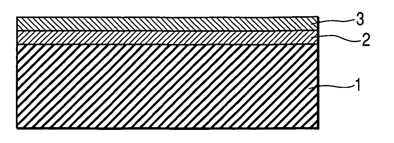
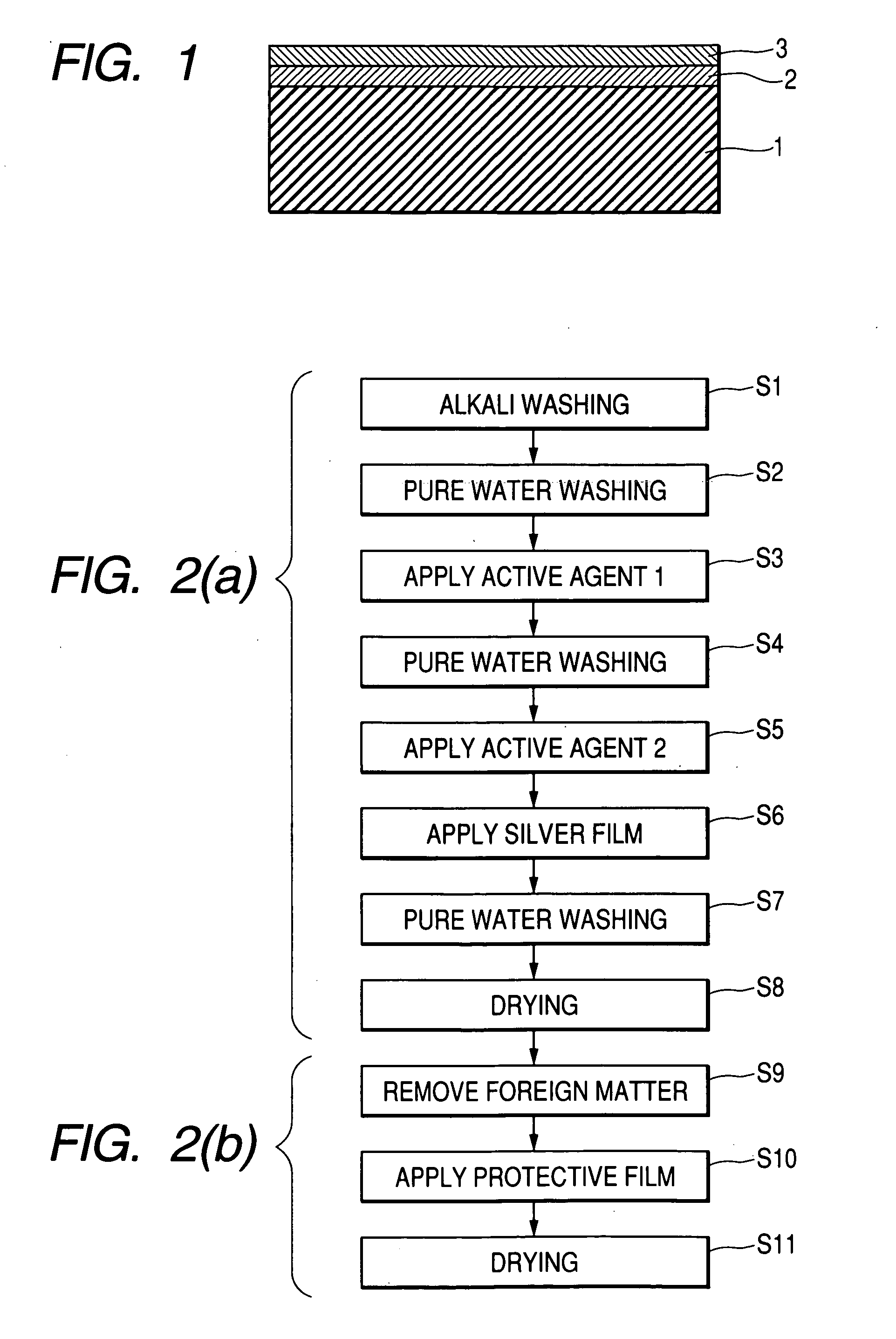
[0024] Embodiments of the present invention will hereinafter be set forth in detail with reference to drawings. FIG. 1 is a sectional view of a reflecting mirror according to one embodiment of the present invention. As shown in FIG. 1, the reflecting mirror comprises a substrate 1 having a flat surface, a reflecting film (layer) 2 formed on the flat substrate surface, and a protective film (layer) 3 that covers the surface of the reflecting film to prevent the corrosion of the reflecting film. Here, the substrate 1 uses glass; the reflecting film (layer) 2 is formed on the substrate by the spray method that makes use of the silver mirror reaction.

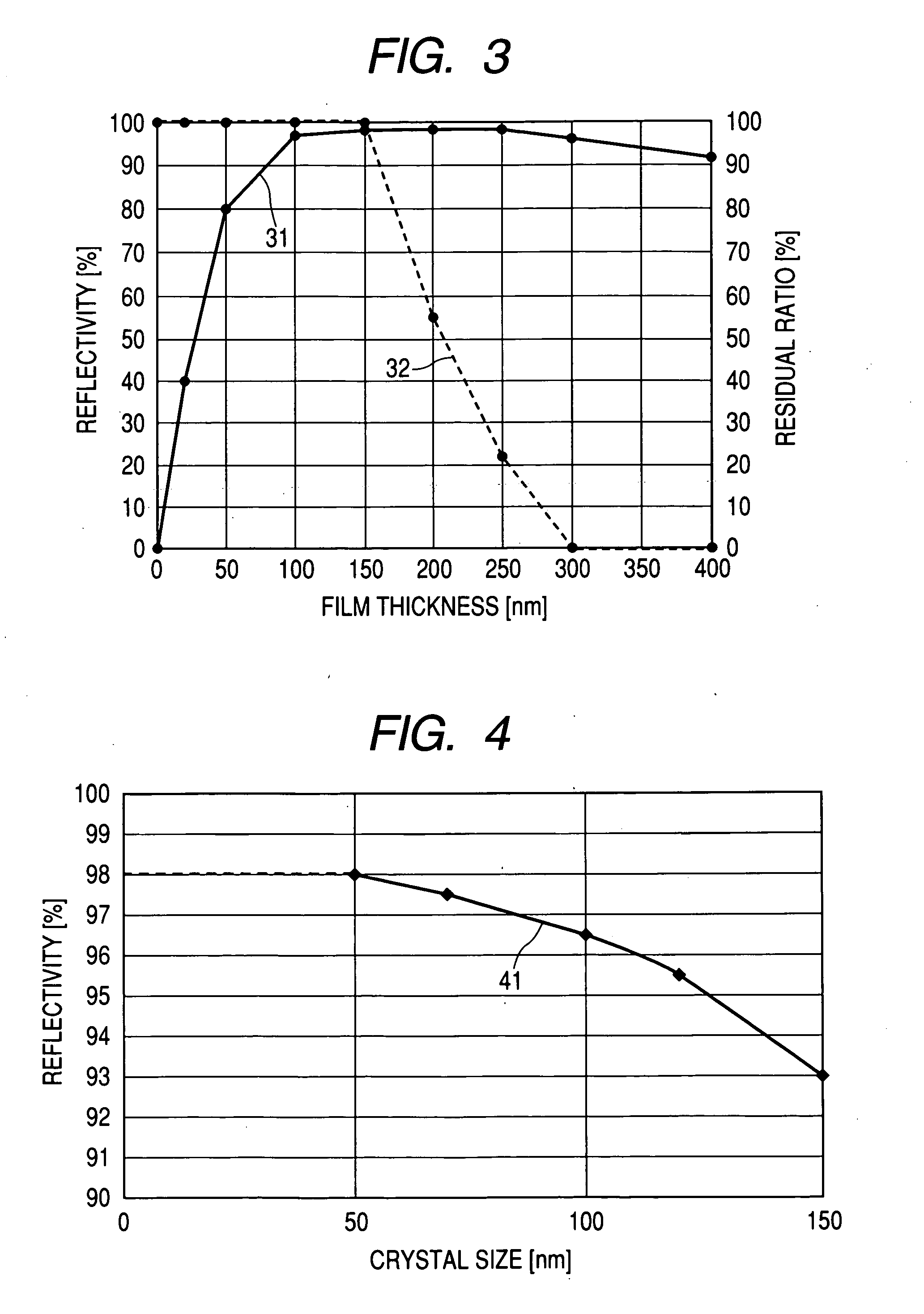
[0025] The term “surface roughness” described below stands for minute bumps and dips formed on the silver reflection surface; the bumps and dips are formed attributable to the crystal of the metal deposited when the reflection surface is formed on the substrate. This crystal size varies depending on chemical conditions of chemical material...


PUM


Abstract

The present invention is directed to the provision of a reflecting mirror that suppresses decreases in the resolution performance and contrast performance by decreasing the mean surface roughness. In a projection type image display apparatus including a projector lens that expansion projects the image light from an image generating source and a reflecting mirror that guides the image light from the projector lens to the back face of the screen, according to the present invention, a silver reflecting surface (2) is formed on the substrate (1) of the reflecting mirror, a protective layer (3) of a transparent resin is formed thereon, and the mean surface roughness of the silver reflecting layer is made to be 1.8 nm or less.

Description

CLAIM OF PRIORITY [0001] The present application claims priority from Japanese Application serial no. JP 2004-141803 field on May 12, 2004, the content of which is hereby incorporated by reference into this application. BACKGROUND OF THE INVENTION [0002] (1) Field of the Invention [0003] The present invention relates to a reflecting mirror for guiding image light expansion-projected by a projector lens to the back face of a screen, and to a projection type image display apparatus using the reflecting mirror. [0004] (2) Description of the Related Art [0005] A projection type image display apparatus utilizes a reflecting mirror for the downsizing of the set; the reflecting mirror involves reflecting image light from an image generating source such as a CRT, or a liquid crystal panel for changing the light path, and then guiding the image light to the back face of a transmission screen. The metal reflection film (metal reflection layer) of the reflecting mirror conventionally uses alum...

Claims


Application Information

Patent Timeline
IPC IPC(8): G03B21/00G02B5/08G03B21/10G03B21/14G03B21/28H04N5/74
CPCG02B5/0808H04N5/7416G03B21/28G03B21/10
Inventor ADACHI, KEINISHIMURA, SADAYUKIHIRATA, KOJIMASUOKA, NOBUO
Owner HITACHI LTD
Learn More