Magnetic element for multi-phase and method of manufacturing the same
a multi-phase, magnetic element technology, applied in the field of magnetic elements, can solve the problems of large eddy current loss, difficult use at large current, and difficult miniaturization and high efficiency of equipmen
- Summary
- Abstract
- Description
- Claims
- Application Information
AI Technical Summary
Problems solved by technology
Method used
Image
Examples
exemplary embodiment 1
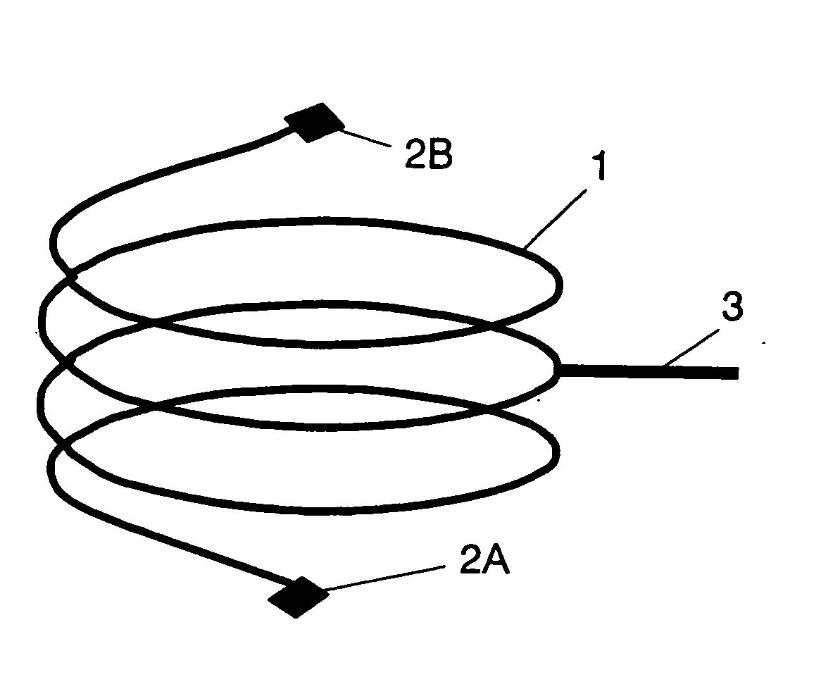
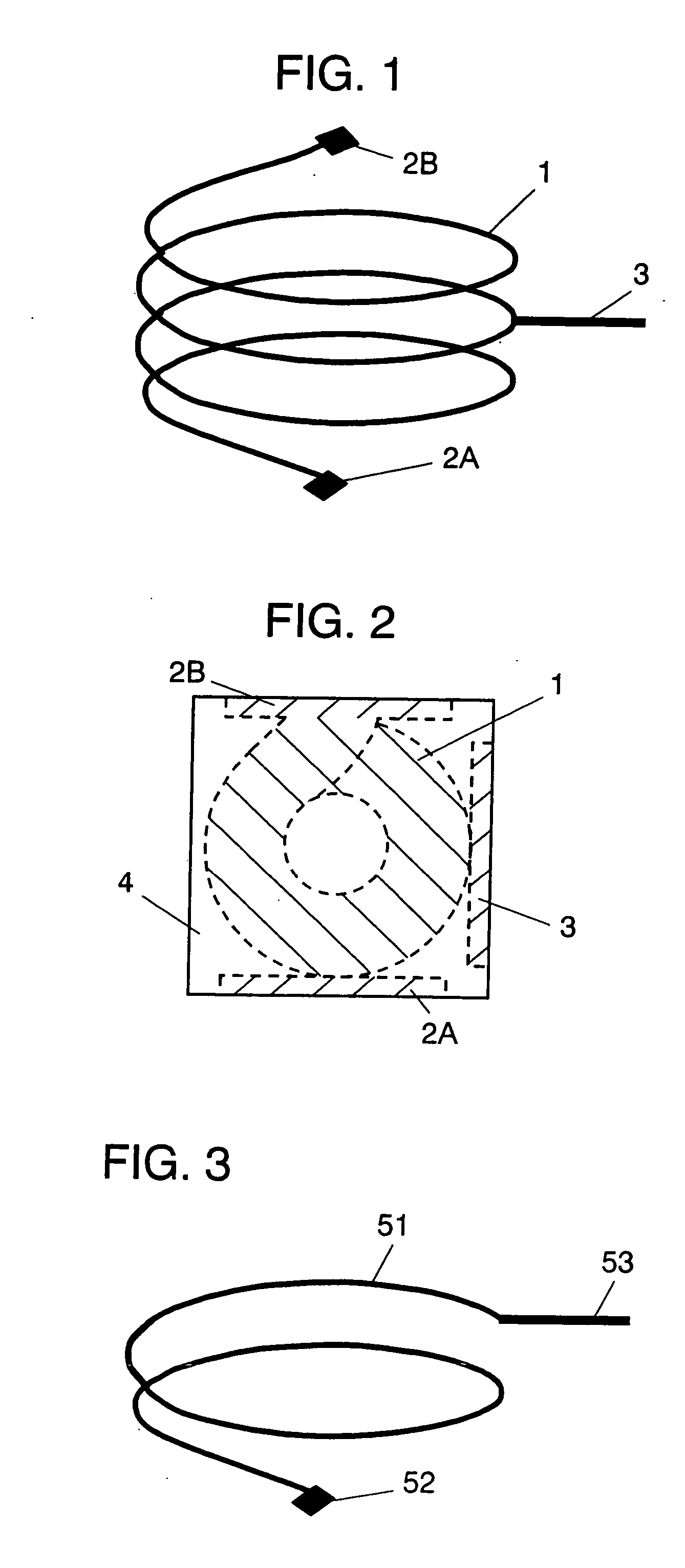
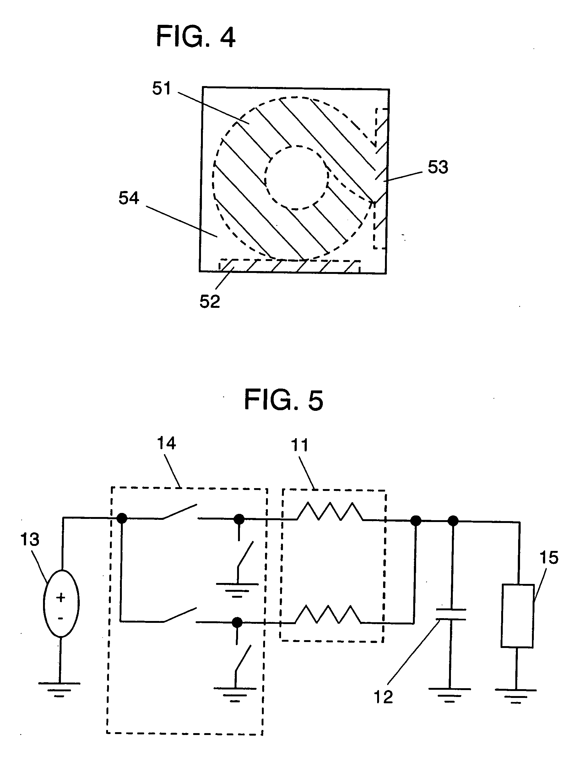
[0026]FIG. 1 is the schematic perspective view of the coil for explaining a structure of the coil contained in the multi-phase magnetic element in the first exemplary embodiment of the present invention. FIG. 2 is the see-through view of the upper surface for explaining a structure of the magnetic element in the present embodiment. The magnetic element according to the present embodiment has a coil 1 and a composite magnetic material 4. The coil 1 has input terminals 2A, 2B and an output terminal 3. FIGS. 3 and 4 are the schematic perspective view of the coil and the see-through view of the upper surface of the magnetic element for explaining a shape of the coil and a structure of the magnetic element in the comparative examples of the prior art. The prior magnetic element has a coil 51 and a composite magnetic material 54. The coil 51 has an input terminal 52 and an output terminal 53.
[0027] The following description will explain a case of using the magnetic element according to t...
exemplary embodiment 2
[0042]FIG. 6 is the schematic perspective views of the coils for explaining the coil structure contained in the multi-phase magnetic element in the second exemplary embodiment of the present invention. FIGS. 7A, 7B are respectively the see-through view of the upper surface of the magnetic element and the cross sectional view of the same for explaining the magnetic element in the present embodiment. The magnetic element according to the present embodiment has an upper coil 21A, a lower coil 21B and a composite magnetic material 24. The upper coil 21A and the lower coil 21B have respectively input terminals 22A, 22B and output terminals 23A, 23B. FIG. 8 is the schematic perspective view of the coil for explaining a structure of the coil contained in the multi-phase magnetic element in the comparative examples of the prior art. FIGS. 9A, 9B are respectively the see-through view of the upper surface of the magnetic element and the cross sectional view of the same for explaining the stru...
exemplary embodiment 3
[0054]FIG. 11 is the see-through view of the upper surface of the magnetic element in the third exemplary embodiment of the present invention. FIG. 10 is the schematic perspective view of each coil contained in the magnetic element in FIG. 11. The coil 31 has an input terminal 32 and an output terminal 33. In FIG. 11, since a plurality of neighboring coils 31 direct in the same turning direction, the magnetic flux flows to have the negative coupling in the coil centers of the respective neighboring coils buried in a composite magnetic material 34. Such a structure brings about the miniaturized multi-phase magnetic element having especially excellent property of DC superposed.
[0055] The following description will state the specific structure of the magnetic element and properties thereof. The present embodiment employs, as a raw material of the composite magnetic material 34, ingot pulverized particles composed of the metallic magnetic particles having compositions shown in Table 3....
PUM
| Property | Measurement | Unit |
|---|---|---|
| Magnetism | aaaaa | aaaaa |
Abstract
Description
Claims
Application Information
 - R&D Engineer
- R&D Manager
- IP Professional
- Industry Leading Data Capabilities
- Powerful AI technology
- Patent DNA Extraction
Browse by: Latest US Patents, China's latest patents, Technical Efficacy Thesaurus, Application Domain, Technology Topic, Popular Technical Reports.
© 2024 PatSnap. All rights reserved.Legal|Privacy policy|Modern Slavery Act Transparency Statement|Sitemap|About US| Contact US: help@patsnap.com


