Barrier device with external reinforcement structure

Inactive Publication Date: 2005-11-17
TRINITY HIGHWAY PRODS
View PDF25 Cites 21 Cited by
  • Summary
  • Abstract
  • Description
  • Claims
  • Application Information

AI Technical Summary

Benefits of technology

[0009] This invention is directed to a barrier device comprising a top wall, a bottom wall, opposed end walls, and, opposed side walls interconnected to form a hollow interior in which a pair of spaced openings are formed which extend between the side walls. An external reinforcement structure is provided to enhance the structural integrity of the barrier device, including first and second beams each extending along one of the side walls which are connected to one anothe

Problems solved by technology

One problem with highway barriers of the type described above is the high weight of reinforced concrete.
Additionally, concrete barriers have little or no ability to absorb shock upon impact, and have a high friction factor.
This increases the damage to vehicles which collide with such barriers, and can lead to s

Method used


Image

  • Barrier device with external reinforcement structure
  • Barrier device with external reinforcement structure
  • Barrier device with external reinforcement structure

Examples


Example

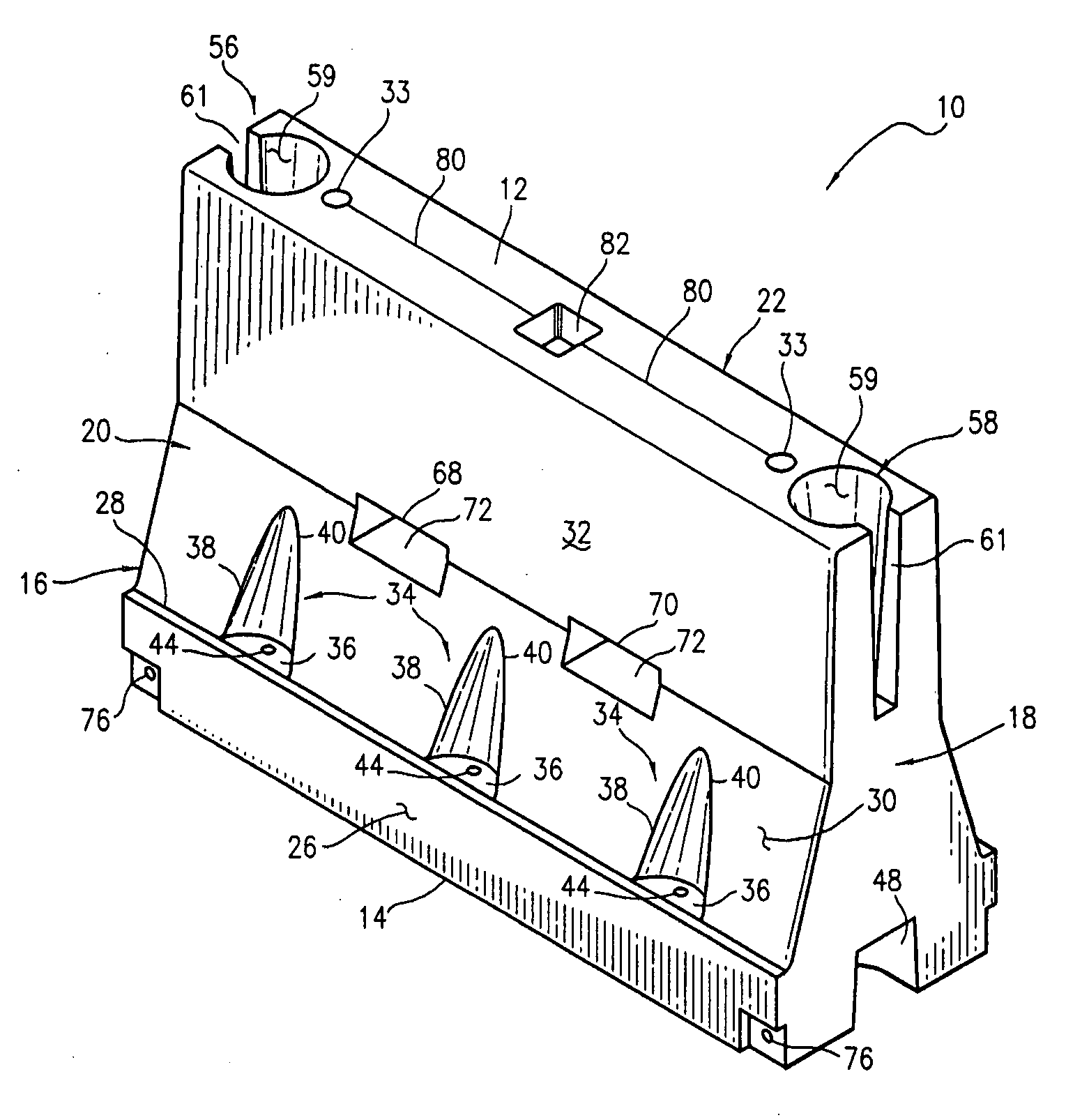
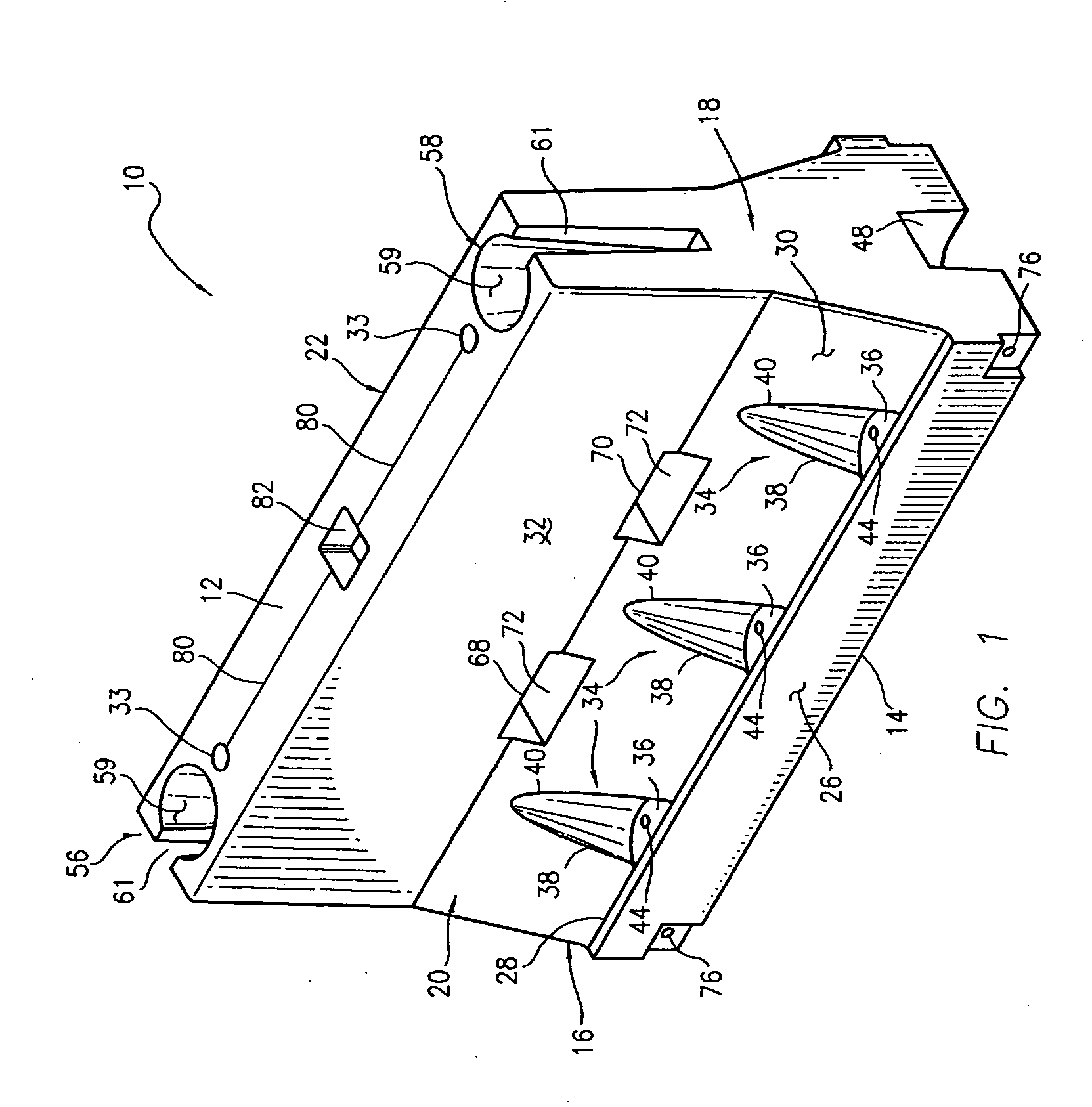
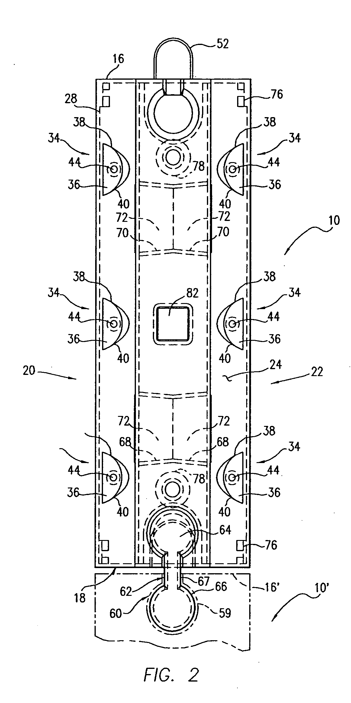
[0048] Referring initially to FIGS. 1-4, the barrier device 10 of this invention comprises a top wall. 12, a bottom wall 14, opposed end walls 16, 18, and, opposed side walls 20, 22 which are interconnected to collectively define a hollow interior 24. In the presently preferred embodiment, each of the walls 12-22 are formed of a semi-rigid plastic material chosen from the group consisting of low density polyethylene, high density polyethylene, acrylonitrile or butadiene styrene, high impact styrene, polycarbonates and the like. These plastic materials are all inherently tough and exhibit good energy absorption characteristics. They will also deform and elongate, but will not fail in a brittle manner at energy inputs which cause other materials to undergo brittle failure. The surfaces of these types of plastic materials are inherently smoother than materials from which other barriers are typically constructed, therefore creating less friction and reducing the likelihood of serious ab...


PUM


Abstract

A barrier device comprises a top wall, a bottom wall, opposed end walls and opposed side walls interconnected to form a hollow interior in which a pair of spaced openings are formed which extend between the side walls. An external reinforcement structure is provided to enhance the structural integrity of the barrier device, including first and second beams each located along one of the side walls which are connected to one another by a mounting device extending through the openings in the hollow interior, or, alternatively, are mounted within a seat formed in each side wall between the opposed ends of the barrier device. The beams of one barrier device are connected end-to-end with the beams of adjacent barrier devices to form an essentially continuous wall of barriers which resist disengagement from one another and exhibit improved resistance to being broken apart upon impact by a vehicle.

Description

RELATED APPLICATION [0001] This application is a continuation-in-part of U.S. patent application Ser. No. 10 / 669,998, filed Sep. 24, 2003, which is a divisional of U.S. patent application Ser. No. 10 / 033,974, filed Dec. 19, 2001, now U.S. Pat. No. 6,666,616, issued Dec. 23, 2003 in the name of Leo J. Yodock, III, Leo J. Yodock, Jr., and Guy C. Yodock, entitled “Barrier Device With External Reinforcement.”FIELD OF THE INVENTION [0002] This invention relates to barrier devices for vehicular and vessel traffic control, soil erosion containment, impact attenuation and the like which can be interconnected with one another to define a continuous barrier wall structure and / or connected in various combinations to form energy-absorbing cells, and, more particularly, to barrier devices formed of a light weight plastic having side wall which receive and mount external reinforcement structure in the form of a pair of beams each extending along the length of one of the side walls. BACKGROUND OF ...

Claims


Application Information

Patent Timeline
IPC IPC(8): E01F13/00E01F15/08
CPCE01F15/083E01F15/088E01F15/086
Inventor YODOCK, LEO J. IIIYODOCK, LEO J. JR.YODOCK, GUY C.
Owner TRINITY HIGHWAY PRODS
Why Eureka
Try Eureka