Remote terminal unit and remote monitoring and control system

a remote terminal and control system technology, applied in the field of remote terminal units and remote monitoring and control systems, can solve problems such as severe damage to crops, and achieve the effect of easy configuration of the remote terminal units

Inactive Publication Date: 2005-11-17
CRITICAL WIRELESS CORP
View PDF18 Cites 42 Cited by
  • Summary
  • Abstract
  • Description
  • Claims
  • Application Information

AI Technical Summary

Benefits of technology

[0006] One preferred form of remote terminal unit according to the present invention includes a substantially planar main circuit substrate and a substantially planar wireless transceiver unit. A processor and a terminal block component are both mounted on the main circuit substrate. An offset interface is connected between the main circuit substrate and the wireless transceiver unit and positions the main circuit substrate with respect to the wireless transceiver unit. In this connected position, the main circuit substrate extends along a plane substantially parallel to the plane of the wireless transceiver unit and is separated from the plane of the wireless transceiver unit by an offset distance. A battery arrangement is mounted on the remote terminal unit with a major surface of the battery arrangement substantially abutting a major surface of the wireless transceiver unit and having a first end surface adjacent to an end of the main circuit substrate. Among other benefits, this arrangement of components in the remote terminal unit provides a very compact structure that ordinarily may be housed easily within a housing of some device or system to be monitored.
[0008] In further preferred forms of the remote terminal unit, the unit includes a serial interface such as an RS-232, RS-485, or other standard serial interface. In these forms of the invention, the processor may also function to drive a configuration interface on a standard terminal emulator in communication with the remote terminal unit through the serial interface. This configuration interface allows a user to easily configure the remote terminal unit. In yet other forms of the invention, the processor or a separate processor may implement a telemetry controller for responding to a plain text telemetry control protocol.

Problems solved by technology

A failure of an automated irrigation system may deprive a crop of water at a critical time and cause severe damage to the crop.

Method used


Image

  • Remote terminal unit and remote monitoring and control system
  • Remote terminal unit and remote monitoring and control system
  • Remote terminal unit and remote monitoring and control system

Examples


Embodiment Construction

[0023] The claims at the end of this application set out novel features which the Applicant believes are characteristic of the invention. The various advantages and features of the invention together with preferred modes of use of the invention will best be understood by reference to the following description of illustrative embodiments read in conjunction with the drawings introduced above.

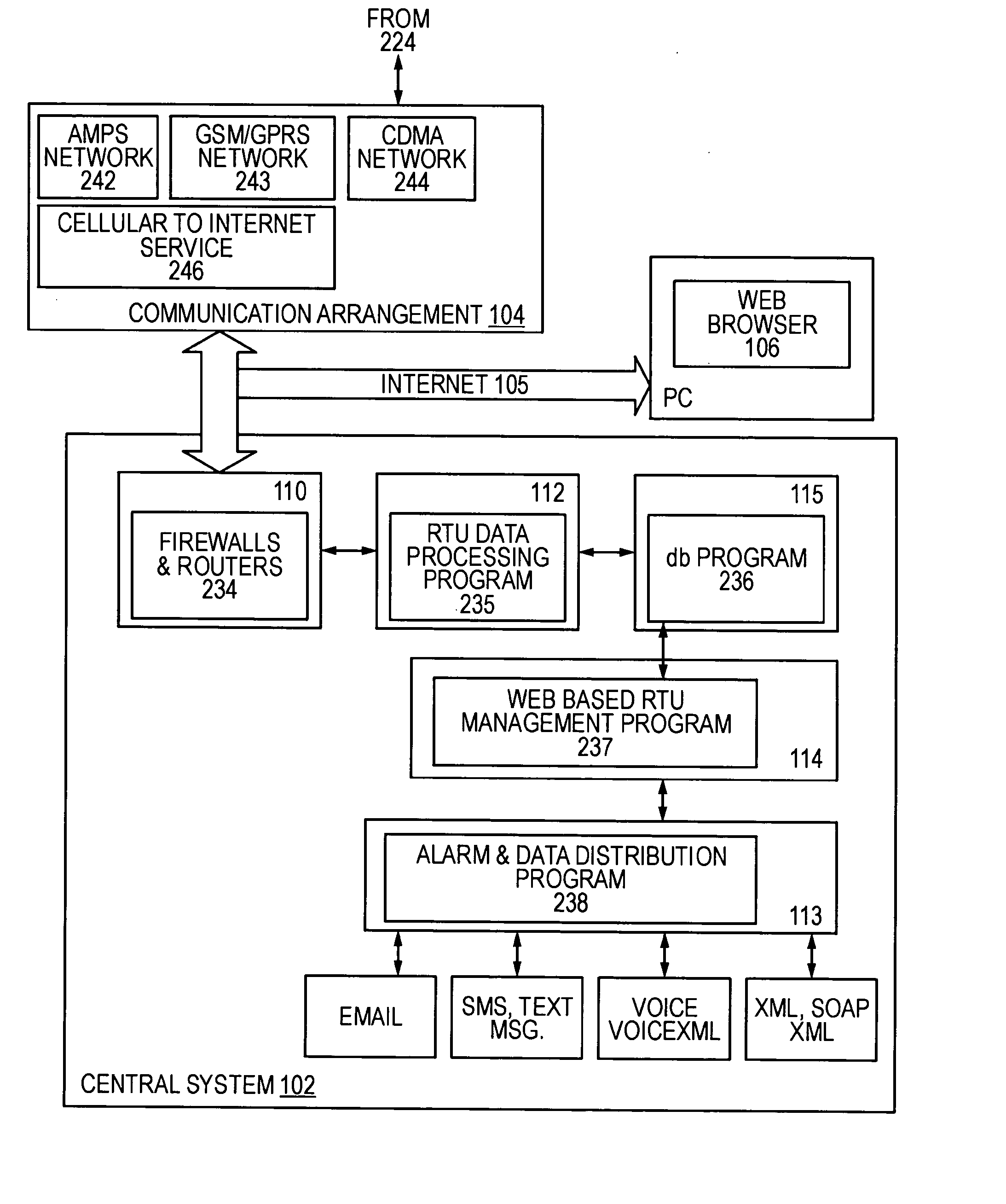
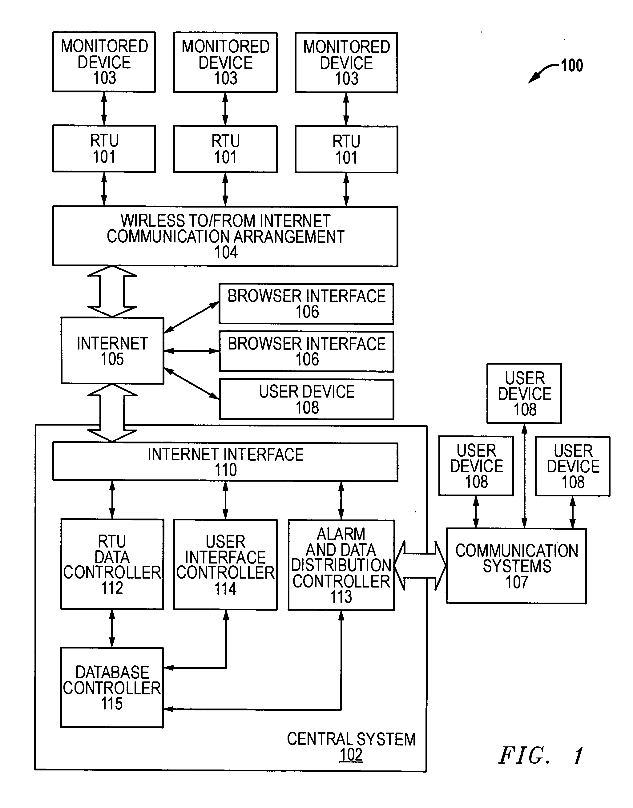
[0024] A remote monitoring and alerting system 100 includes one or more remote terminal units 101 and a central system 102. Each remote terminal unit or RTU 101 is adapted to be connected to some device 103 to be monitored or controlled remotely through system 100. Central system 102 is adapted to communicate with the various RTUs 101 through a separate communications system, preferably including a wireless to Internet communication arrangement 104 and the Internet 105. Central system 102 is also adapted to provide a web-based user interface to system 100 that a user may access through a suitabl...


PUM


Abstract

A remote monitoring and alerting system includes one or more remote terminal units and a central system, with both the central system and each remote terminal unit adapted to send and receive data across a communications network. Each remote terminal unit includes a processor and wireless transmitter in a compact arrangement that allows the unit to be placed conveniently in a housing associated with some remote device to be monitored. The central system includes a data collection and manipulation controller for receiving, processing, and storing data received from each remote terminal unit across the communications network. Both a user messaging controller and a user interface controller are also included in the central system. The user messaging controller transmits user messages through a suitable interface to one or more user designated devices in response to a remote terminal unit message received from the remote terminal unit. The user interface controller provides a user interface between a user of the remote monitoring and alerting system and the central system.

Description

CROSS-REFERENCE TO RELATED APPLICATION [0001] This application is related to U.S. provisional patent application No. 60 / 567,629, filed May 3, 2004, entitled “REMOTE TERMINAL UNIT AND REMOTE MONITORING AND CONTROL SYSTEM,” the entire content of which is hereby incorporated herein by this reference. The Applicant hereby claims the benefit of this provisional application under 35 U.S.C. §119(e).TECHNICAL FIELD OF THE INVENTION [0002] The invention relates to systems for remotely monitoring and controlling devices and for distributing alarms or notifications based on events at the remotely monitored devices. BACKGROUND OF THE INVENTION [0003] Numerous types of equipment are adapted to operate in an automated fashion without any local operator. Some of these types of equipment may operate in remote locations. Commercial agricultural irrigation systems such as pivot irrigation systems are examples of complex automated systems that are commonly located at some remote location. These types ...

Claims


Application Information

Patent Timeline
Patent Type & Authority Applications(United States)
IPC IPC(8): H04M11/00H04M11/04
CPCH04M11/04
Inventor FISHER, JEFFREY L.
Owner CRITICAL WIRELESS CORP
Why Eureka
Try Eureka