Drive guide device

Active Publication Date: 2005-11-24
THK CO LTD
View PDF6 Cites 18 Cited by
  • Summary
  • Abstract
  • Description
  • Claims
  • Application Information

AI Technical Summary

Benefits of technology

[0035] If a laminated glass-epoxy resin material is used for the absorbing member, as stated above, a deformation of the heatsink is absorbed easily. That is, the laminated glass-epoxy resin material exhibits strong rigidity in the lamination direction (thickness direction) and weak rigidity in a

Problems solved by technology

The increase in the preload involves the problem that the rolling resistance to the rolling elements increases, leading to shortening of the lifetime of the drive guide apparatus.
In apparatus that are required to exhibit high accuracy, e.g. precision measuring apparatus, a light preload necessary for removing play is applied because the apparatus cannot perform the desired function if there is play.
That is, insufficient dynamic rigidity of a machine tool, for example, causes chatter dur

Method used


Image

  • Drive guide device
  • Drive guide device
  • Drive guide device

Examples


Embodiment Construction

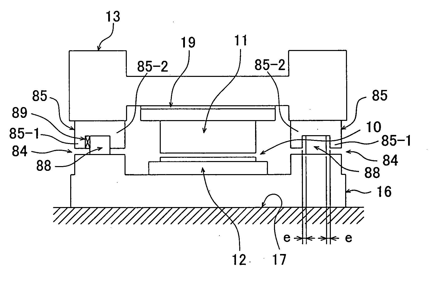
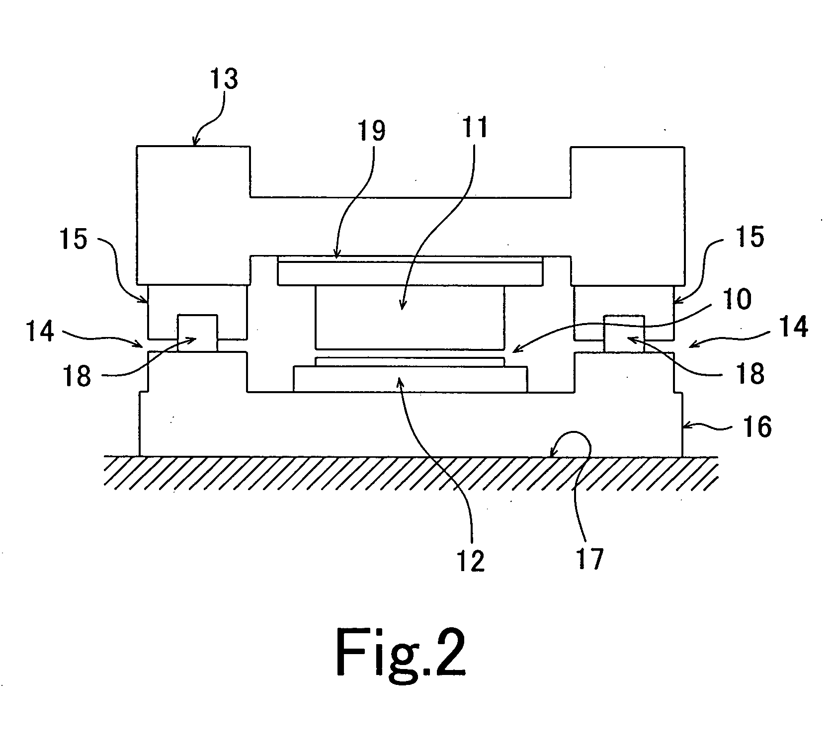
[0066]FIG. 2 is a diagram showing schematically a structural example of a first embodiment of the drive guide apparatus according to the present invention. In the figure, a linear motor 10 comprises a primary side 11 and a secondary side 12. The primary side 11 is an energized side including armature coils. The secondary side 12 is a non-energized side having magnets, etc. The primary side 11 is connected through a table 13 to moving blocks 15 each serving as a moving member of a guide mechanism 14. The secondary side 12 of the linear motor 10 is secured to a base 16. The base 16 is secured to the top of a surface plate 17. In this regard, the drive guide apparatus according to the present invention is the same as the conventional example shown in FIG. 1.

[0067] The base 16 is provided thereon with two parallel rails 18 constituting the guide mechanism in combination with the moving blocks 15. The moving blocks 15 move along the rails 18 in response to driving force obtained from th...


PUM


Abstract

The present invention provides a drive guide apparatus capable of ensuring an increased lifetime by preventing heat generated from a primary side of a linear motor from being transferred to a rail or a moving member of a guide mechanism to which the primary side of the linear motor is connected, thereby preventing variation of rolling resistance or sliding resistance of the guide mechanism.
The drive guide apparatus has a linear motor 10 and a guide mechanism 14 that has a rail 18 and a moving member (moving block 15) provided to be movable relative to the rail 18. A primary side 11 of the linear motor 10 is connected to the rail 18 or the moving member (moving block 15) of the guide mechanism 14. Thermal insulating means (thermal insulators 19 and recess 20) for blocking heat generated from the primary side 11 of the linear motor 10 is provided between the primary side 11 and the rail 18 or the moving member (moving block 15) of the guide mechanism to which the primary side 11 is connected directly or indirectly.

Description

TECHNICAL FIELD [0001] The present invention relates to a drive guide apparatus that has a guide mechanism including a rail and a moving member provided to be movable relative to the rail and that uses a linear motor as a driving means. BACKGROUND ART [0002] Conventional drive guide apparatuses of this type are disclosed in Japanese Patent Post-Exam Publication No. Hei 7-106053 and Japanese Patent Application Unexamined Publication (KOKAI) No. 2001-99151. FIG. 1 is a diagram showing schematically the arrangement of a conventional drive guide apparatus of the type described above. [0003] In the figure, a linear motor 100 comprises a primary side 101 and a secondary side 102. The primary side 101 is an energized side including armature coils. The secondary side 102 is a non-energized side having magnets, etc. The primary side 101 is connected through a table 103 to moving blocks 105 each serving as a moving member of a guide mechanism 104. The secondary side 102 of the linear motor 10...

Claims


Application Information

Patent Timeline
IPC IPC(8): H02K5/173H02K9/22H02K41/02
CPCF16C29/06H02K5/18H02K7/08H02K9/00H02K9/22H02K41/031H02K9/02H02K9/227
Inventor MIYAMOTO, TAROASO, TOSHIYUKIYAMANAKA, SHUHEINAKAYAMA, WATARU
Owner THK CO LTD
Why Eureka
Try Eureka